Check patentability & draft patents in minutes with Patsnap Eureka AI!

A conveyor belt lane change structure

A conveyor belt and drive belt technology, applied in the field of automation, can solve the problems of expensive, easy to damage, complex structure, etc., and achieve the effect of simple structure, low price, and not easy to damage

Inactive Publication Date: 2016-01-06
CCTEG COAL ENG & TRADING +4
View PDF6 Cites 0 Cited by
  • Summary
  • Abstract
  • Description
  • Claims
  • Application Information

AI Technical Summary

Problems solved by technology

[0002] Conveyor belts are widely used in various machinery. Its function is to transport objects and eliminate the labor of manual handling. It is an indispensable part of many automated machinery. Sometimes the conveyor belt assembly line needs to separate the objects that come in from the same conveyor belt. At this time, it is necessary Lane change, the existing conveyor belt lane change structure is complicated, expensive and easy to damage

Method used


Image

  • A conveyor belt lane change structure
  • A conveyor belt lane change structure
  • A conveyor belt lane change structure

Examples


Embodiment 1

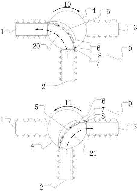
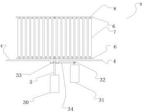
[0017] like Figure 1-3 is a schematic diagram of this embodiment,

[0018] like figure 1 As shown, the process of changing the lane from the transmission channel 20 to the transmission channel 21 is embodied.

[0019] like figure 1 As shown, the lane changing mechanism composed of the disc 4 and the arc baffle 9 is located in the middle of the output conveyor belt 1 , the input conveyor belt 2 and the output conveyor belt 3 .

[0020] like figure 1 As shown, the arc baffle 9 is located above the disc 4 , and the rotation axis 5 of the arc baffle 9 coincides with the central axis of the disc 4 .

[0021] like figure 1 As shown, when an object needs to be transferred from the input conveyor belt 2 to the output conveyor belt 3, the rotating shaft 5 of the arc baffle 9 is rotated so that the inside of the arc baffle 9 connects the input conveyor belt 2 and the outside of the output conveyor belt 3. , and limit the position of the arc baffle 9; at this time, the ...

Embodiment 2

[0029] Based on the implementation example 1, this implementation example is used as a package sorting application. A scanner is set in the middle of the input conveyor belt 2, which can scan the information of the package on the input conveyor belt, and then reroute according to the target area of ​​the package to realize the package sorting. pick.

[0030] From the content of the invention, implementation example 1, appendix figure 1 It can be seen that the main disclosure objects of the present invention are those skilled in the art who have basic knowledge of mechanical principles. In order to highlight the core content of the present invention, that is, the lane changing principle of a conveyor belt lane changing structure of the present invention; this description does not provide some unnecessary foundations. Knowledge points are described, but those skilled in the art with basic knowledge of mechanical principles can figure 1 After understanding the lane-changing ...


PUM


Abstract

The invention discloses a track changing structure of a conveyor belt. The track changing structure mainly comprises a disc and an arc baffle, wherein the disc is rotatable with the rotating direction variable, and the arc baffle is located above the disc and rotatable and can limit positions according to needs; a rotating shaft of the disc and a rotating shaft of the arc baffle coincide with the center axis of the disc, and many rollers are arranged on the inner side of the arc baffle. In the track changing process, the rotating shaft of the arc baffle is rotated, so that two outer sides of the conveyor belt to be communicated are connected through the inner side of the arc baffle, the positions are limited, and then the disc is rotated according to the conveying direction of articles so that tracks can be changed for conveying. The track changing structure is characterized in that the track changing structure is created, and the mode that the arc baffle is matched with the rotating direction of the disc is prominent in novelty. The track changing structure has the advantages of being capable of changing the tracks for the conveying belt, simple in structure, not prone to being damaged, low in cost and capable of being applied to production lines on a large scale.

Description

technical field [0001] The invention belongs to the field of automation, and in particular relates to a conveyor belt lane changing structure. Background technique [0002] Conveyor belts are widely used in various machinery. Its function is to transport objects and eliminate the labor of manual handling. It is an indispensable part of many automated machinery. Sometimes the conveyor belt assembly line needs to separate the objects that come from the same conveyor belt. Lane change, the existing conveyor belt lane change structure is complex, expensive and easy to damage. SUMMARY OF THE INVENTION [0003] The purpose of the present invention is to provide a conveyor belt lane changing structure in view of the deficiencies of the prior art, which has a simple structure and low cost. [0004] The invention uses the following technical solutions: a conveyor belt lane changing structure, comprising a disc and an arc baffle; the disc can be rotated, and the rotation dire...

Claims


Application Information

Patent Timeline
Patent Type & Authority Patents(China)
IPC IPC(8): B65G47/52
CPCB65G47/52B65G2207/30
Inventor 刘文郁赵鑫殷卫峰李铮刘永强杨雪成王志勇杜保平石亮禾文王小刚王滨张豫龙曹颖丽陈凤娇殷国强殷伟伟董振
Owner CCTEG COAL ENG & TRADING
Features
  • R&D
  • Intellectual Property
  • Life Sciences
  • Materials
  • Tech Scout
  • Unparalleled Data Quality
  • Higher Quality Content
  • 60% Fewer Hallucinations
Learn More