Device for reducing pressure and velocity of flowing fluid

A deceleration device and fluid flow technology, which is applied in the direction of valves, devices for absorbing fluid energy, valve devices, engine components, etc., can solve the problems of adding devices, etc., and achieve the effects of suppressing noise, increasing length, and reducing flow speed and pressure

Inactive Publication Date: 2014-07-23
SDD CO LTD
View PDF19 Cites 4 Cited by
  • Summary
  • Abstract
  • Description
  • Claims
  • Application Information

AI Technical Summary

Problems solved by technology

[0035] And, when increasing the radius of disc, there is the problem of needing to increase the radius of device, and increase the problem of this device size

Method used


Image

  • Device for reducing pressure and velocity of flowing fluid
  • Device for reducing pressure and velocity of flowing fluid
  • Device for reducing pressure and velocity of flowing fluid

Examples


Embodiment Construction

[0073] Next, the decompression and deceleration device for flowing fluid of the present invention will be described with reference to the drawings. In the following embodiments, a valve is described as a fluid processing device, but it is not limited to this valve, and it should be understood that other devices having a high pressure drop ratio applied to the inlet side and outlet side conditions are also included.

[0074] basic structure

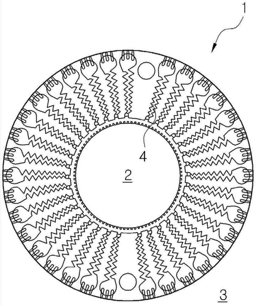
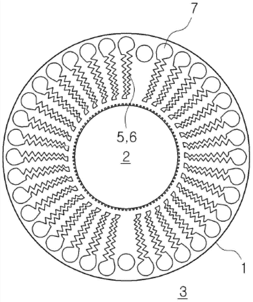
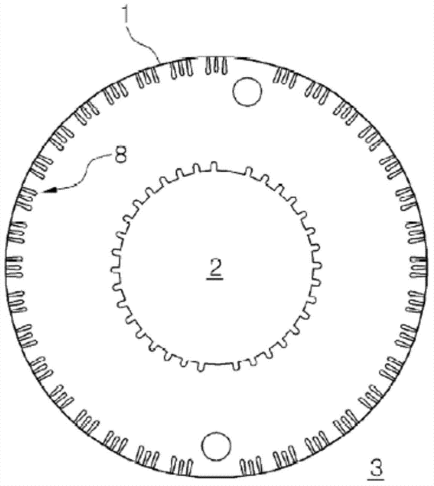
[0075] Figure 6 In order to show the longitudinal sectional view of the valve structure installed with the decompression and deceleration device of the flowing fluid of the present invention, Figure 7 A cross-sectional view showing the basic structure of a decompression and deceleration device for flowing fluid, Figure 8 to Figure 10 A drawing showing the basic structure of a device for depressurizing and decelerating a flowing fluid, Figure 11 and Figure 12 It is a drawing showing the arrangement state of the channel u...


PUM


Abstract

The present invention relates to a device for reducing the pressure and the velocity of a flowing fluid. According to the present invention, a cage has discs having through-holes which come into close contact with an outer surface of a plug. The discs are stacked in a direction of a central shaft of the cage. Flow passage portions are formed on the stacked discs, wherein the flow passage portions communicate with the outer surfaces of the discs and the inner surfaces which correspond to the through-holes so as to form flow passages between the stacked discs, and the direction of the flow passages changes to a circumferential direction and a vertical direction on the stacked discs. Additionally, the discs are stacked by applying one or more flow passage portion patterns based on the number of times the direction of the flow passages changes and the number of the flow passage portions to the discs so as to control the increasing velocity of a fluid relative to an opening degree formed according to an upward movement of the plug.

Description

technical field [0001] The present invention relates to a decompression and deceleration device for flowing fluid, and relates in detail to a device that can effectively reduce the pressure passing through the device under the condition that the pressure difference and high step-down ratio are suitable for the inlet side and the outlet side of fluid processing devices such as valves. The pressure of the flowing fluid, and limit the flow velocity, and suppress the noise, vibration, cavitation, erosion and other side effects caused by the flowing fluid. The decompression and deceleration device of the flowing fluid. Background technique [0002] Generally speaking, under the extreme conditions of high pressure reduction ratio, in the field that requires the control accuracy of pressure or flow rate, in order to properly control the flow rate and pressure of the fluid, and maintain a long life and good condition, use a (Orifice), labyrinth (Labyrinth) or curved (Tortuous) flow ...

Claims


Application Information

Patent Timeline
Patent Type & Authority Applications(China)
IPC IPC(8): F16K47/14F16K47/04
CPCF16K47/08Y10T137/86759F16K47/04F16K47/14
Inventor 权甲周金永范徐东杓金真弘
Owner SDD CO LTD
Why Eureka
Try Eureka