An Ink Supply System for a Tire Digital Printer

A printer and ink supply technology, which is applied in printing and other directions, can solve the problems of no ink entering the hose, disconnection of the test line, high cost, etc., and achieve the effects of reducing the deformation of the chip contact pin, high-quality printing quality, peace of mind and convenience in use

Active Publication Date: 2017-05-03
HEFEI AIRWREN AUTOMATIC EQUIP CO LTD
View PDF8 Cites 0 Cited by
  • Summary
  • Abstract
  • Description
  • Claims
  • Application Information

AI Technical Summary

Problems solved by technology

[0011] However, the ink supply systems used in all the inkjet printers mentioned above have the following designs: split ink cartridge ink supply system and integrated ink cartridge ink supply system. The system’s ink sacs and hoses have a short service life and are easy to block the nozzles. The integrated ink cartridge ink supply system has a high cost. The thermal foaming nozzles used in it have a short service life, but the hoses often do not enter ink. The above two designs There are the following disadvantages: 1. The ink indicator on the printer is always red, and it will not work when the printer is turned off and on again; 2. The decoder is invalid after decoding the chip of the ink cartridge; 3. The printer does not perform cleaning after pressing the cleaning button; when canceling printing When working, the ink indicator light on the printer is on; when the computer is restarted, the ink indicator light on the printer is on; 4. Repeat the cleaning and testing process
Small ink dots appear on the paper when printing; 5. Large ink spots often appear on the paper when printing; 7. No matter what paper is used for printing, there is always some ink left on the edge of the paper; 8. There is always ink on the paper feed roller of the printer. Some test lines printed with ink stains are always disconnected; 9, and there is a phenomenon of color crossing; 10, the ink cartridge leaks

Method used


Image

  • An Ink Supply System for a Tire Digital Printer

Examples


Embodiment Construction

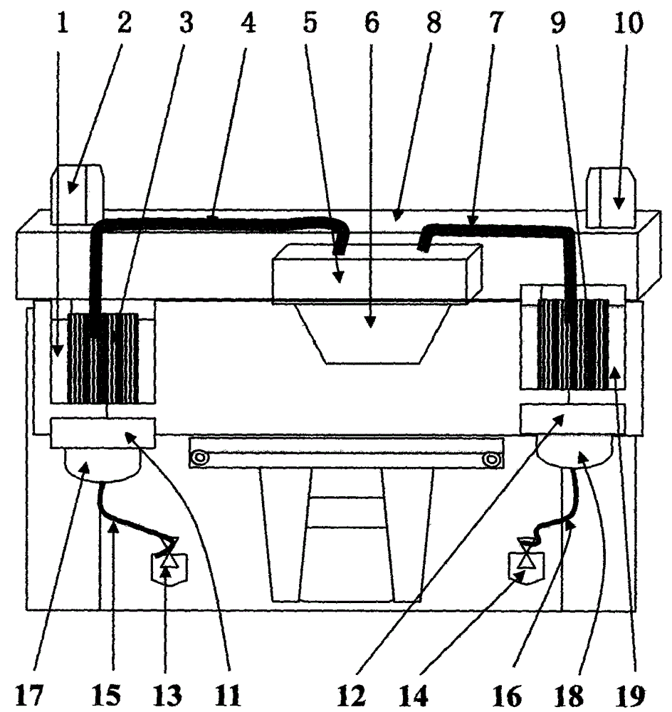
[0023] Reference figure 1 An ink supply system for tire digital printers of the present invention adopts the following technical scheme: It is characterized in that: the printing pressure chamber 5 is provided with a printing nozzle 6 at the lower end, and the printing pressure chamber 5 is connected to the left ink supply tube 4 through the left ink supply tube 4. In the ink tank 3, the upper end of the left ink supply ink sleeve 1 is provided with a left ink exhaust bin 2, and the lower end of the left ink supply 3 is correspondingly provided with a left washing squeegee 11, and the lower end of the left washing squeegee 11 is connected to a left nozzle cleaner 17 The print nozzle 6 is cleaned and sucked by the left ink absorber 13 through the left waste ink suction pipe 15.

[0024] The printing pressure chamber 5 is provided with a right ink supply tube 7 connected to the right ink supply 9, the upper end of the right ink supply ink sleeve 19 is provided with a right ink exha...


PUM


Abstract

An ink supply system for a tire numeric printer comprises a left ink supplier ink sleeve, a left ink exhaust bin, a left ink supplier, a left ink supply pipe, a printing pressure bin, a printing spraying nozzle, a right ink supply pipe, a printing character cart sliding frame, a right ink supplier, a right ink exhaust bin, a left ink cleaning scraping plate, a right ink cleaning scraping plate, a left ink sucker, a right ink sucker, a left waste ink sucking pipe, a right waste ink sucking pipe, a left ink cleaner, a right ink cleaner and a right ink supplier ink sleeve. As the ink supply system commonly composed of a left ink supply structure and a right ink supply structure is used for supplying ink to the printing pressure bin, the printing pressure bin and the printing spraying nozzle jointly act on numeric printing of a tire, the stability of the scientific designing process largely reduces the plugging rate and relieves the problems of ink backflow, ink leakage, deformation of a chip contact pin, damage to a chip, existence of impurities, volatilization and the like, continuous stability of the tire numeric printer is guaranteed, and a user can use the tire numeric printer more conveniently and at ease.

Description

[0001] Technical field: [0002] The invention belongs to the field of tire digital printers, and in particular relates to an ink supply system for tire digital printers. [0003] Background technique: [0004] Most of the ink supply systems of traditional tire digital printers use the siphon principle, that is, in two containers that contain liquid and are connected by a siphon, the liquid always flows from the container with high pressure to the container with low pressure. We know that during the printing process, the ink cartridges of the printer will continuously deliver ink to the nozzles. While delivering the ink, the pressure in the ink cartridges is also decreasing. The same volume of air needs to be drawn in to maintain pressure balance. The ink supply system will The air replenished by the vent of the ink cartridge is replaced with ink. The ink cartridge is also replenished with the same volume of ink while delivering ink to the nozzle. The ink replenished into the inner i...

Claims


Application Information

Patent Timeline
Patent Type & Authority Patents(China)
IPC IPC(8): B41J2/175
Inventor 龙梅
Owner HEFEI AIRWREN AUTOMATIC EQUIP CO LTD
Why Eureka
Try Eureka