Check patentability & draft patents in minutes with Patsnap Eureka AI!

A circular cutting machine

A circulating cutting machine and cutting knife technology, applied in the field of cutting devices, can solve the problems of low cutting efficiency and long cutting time, so as to achieve high cutting efficiency, improve cutting efficiency, and prevent deflection.

Active Publication Date: 2017-04-05
WUHU YINXING AUTO PARTS
View PDF5 Cites 0 Cited by
  • Summary
  • Abstract
  • Description
  • Claims
  • Application Information

AI Technical Summary

Problems solved by technology

This intermittent cutting method takes a long time to cut and the efficiency of cutting is low

Method used


Image

  • A circular cutting machine
  • A circular cutting machine
  • A circular cutting machine

Examples


Embodiment Construction

[0016] In order to make the technical means, creative features, goals and effects achieved by the present invention easy to understand, the present invention will be further elaborated below.

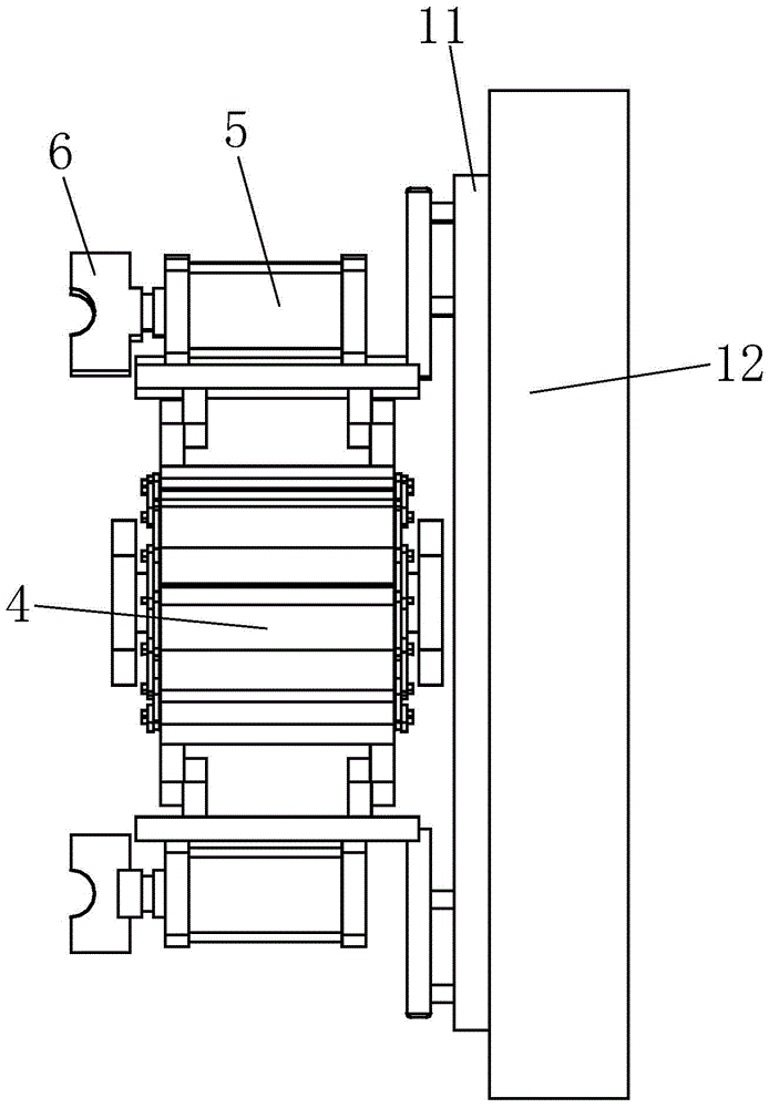
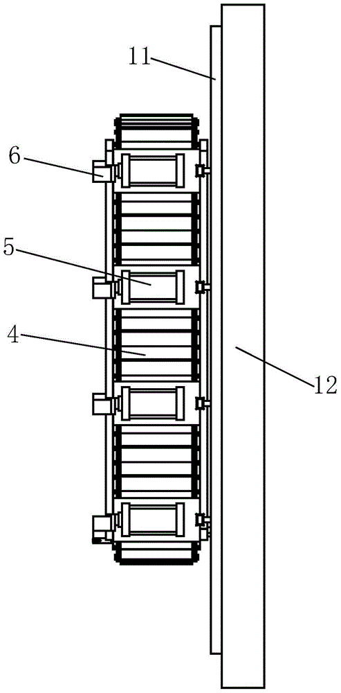
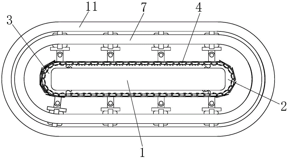
[0017] Such as Figure 1 to Figure 6 As shown, a circular cutting machine includes a fixed side plate 1, a main driving wheel 2, a driven wheel 3, a conveying chain plate 4, a cutting cylinder 5, a cutting head 6, an inner runway guide frame 7, an outer Raceway guide frame 11, side stand base plate 12 and gliding device, described inner raceway type guide frame 7 is distributed in the inner side of outer raceway type guide frame 11, described fixed side plate 1, inner raceway type guide frame 7, outer raceway type guide frame The frames 11 are all fixedly connected to the left side wall of the side-standing base plate 12, and the main driving runner 2 and the driven runner 3 are respectively installed on the rear side and the front side of the fixed side plate 1, and the conveying chain...


PUM


Abstract

The invention relates to a circulating type cutting machine. The circulating type cutting machine comprises a fixed side plate, a driving rotating wheel, a driven rotating wheel, a conveying chain plate, cutting cylinders, cutting cutter heads, an inner race type guide frame, an outer race type guide frame, a side vertical base plate and sliding devices; the inner race type guide frame is distributed at the inner side of the outer race type guide frame; the fixed side plate, the inner race type guide frame and the outer race type guide frame are all fixedly connected with the left sidewall of the side vertical base plate; the driving chain wheel and the driven chain wheel are respectively correspondingly mounted at the front side and the rear side of the fixed side plate; the conveying chain plate wraps the driving rotating wheel and the driven rotating wheel; the cutting cylinders are distributed at equal intervals on the outer side surface of the conveying chain plate in the wrapping direction of the conveying chain plate; the cutting cutter heads are respectively correspondingly mounted on the cutting cylinders; the sliding devices are mounted at the tail parts of the cutting cylinders. The circulating type cutting machine has the advantages of being reasonable in structural design, high in automation degree and high in cutting efficiency; materials can be automatically blanked, so that the cutting efficiency can be increased, and the time for cutting is reduced.

Description

technical field [0001] The invention relates to a cutting device, in particular to a circular cutting machine. Background technique [0002] Existing bar cutting mostly adopts hydraulic cutting equipment, that is, on the one hand, the external conveying equipment is used to drive the bar to realize feeding. After the feeding length reaches a certain value, the cutting equipment can be started, and the hydraulic equipment can be used to realize cutting. deal with. This intermittent cutting method takes a long time to cut off, and the efficiency of cutting off is low. Contents of the invention [0003] Aiming at the above-mentioned technologies, the present invention proposes a device with reasonable structural design, high degree of automation, high cutting efficiency, and capable of automatic cutting, that is, a circular cutting machine. [0004] A circular cutting machine, including fixed side plates, main drive runners, driven runners, conveying chain plates, cutting c...

Claims


Application Information

Patent Timeline
Patent Type & Authority Patents(China)
IPC IPC(8): B23D79/00
Inventor 曹志刚
Owner WUHU YINXING AUTO PARTS
Features
  • R&D
  • Intellectual Property
  • Life Sciences
  • Materials
  • Tech Scout
  • Unparalleled Data Quality
  • Higher Quality Content
  • 60% Fewer Hallucinations
Learn More