Composite bearing deflection limiting device for stirring shaft

A composite bearing and stirring shaft technology, which is applied in the directions of shafts and bearings, bearings, bearing components, etc., can solve the problems that the stirring device cannot work normally, the bearings and the shaft are stuck, etc.

Active Publication Date: 2015-04-22
合肥华升泵阀股份有限公司
View PDF5 Cites 2 Cited by
  • Summary
  • Abstract
  • Description
  • Claims
  • Application Information

AI Technical Summary

Problems solved by technology

If a traditional ball bearing that can only be fixed coaxially is used, the bearing and the shaft will inevitably be stuck due to the above-mentioned deflection of the stirring shaft, resulting in the failure of the entire stirring device to work normally.

Method used


Image

  • Composite bearing deflection limiting device for stirring shaft
  • Composite bearing deflection limiting device for stirring shaft
  • Composite bearing deflection limiting device for stirring shaft

Examples


Embodiment Construction

[0031] Here, the specific structure and workflow of the present invention will be further described through the following specific implementation methods:

[0032] For ease of understanding, the ideal axis of the stirring shaft 10 is first described here as follows: the ideal axis of the stirring shaft 10, that is, regardless of installation errors and other factors that cause the shaft body of the stirring shaft 10 to deflect, is completely ideal when the stirring shaft 10 is in a completely ideal position. The axis in the vertical state of the shaft body.

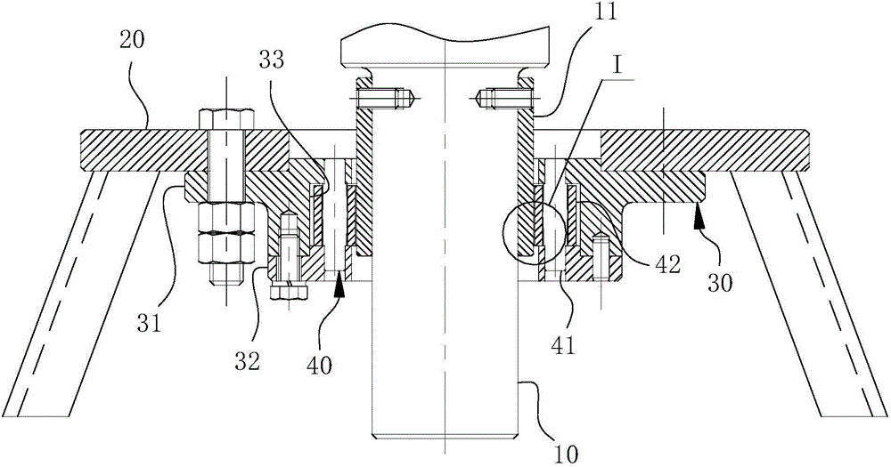
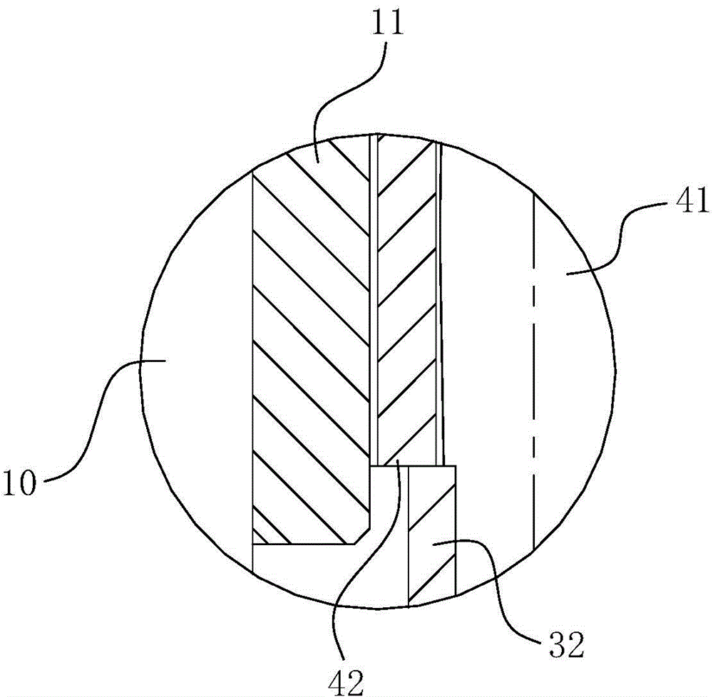
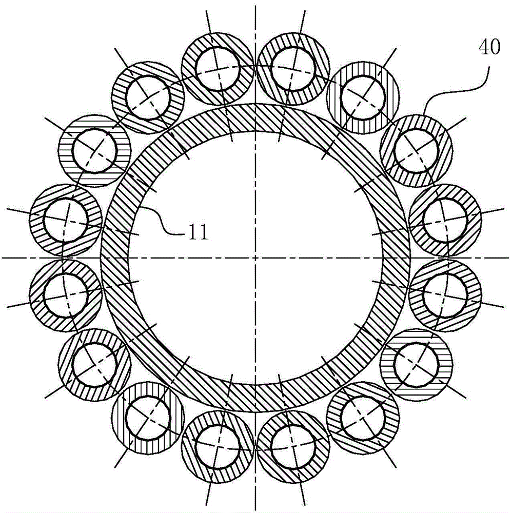
[0033] The specific structure of the present invention is as Figure 1-6As shown, it includes an outer ring sleeve 30 sleeved on the shaft body of the stirring shaft 10 , and the outer ring sleeve 30 is fixed in the inner cavity of the agitator with a support frame 20 . The axis of the outer ring sleeve 30 is arranged coaxially with the ideal axis of the stirring shaft 10, that is, the axis of the stirring shaft 10 in an...


PUM


Abstract

The invention belongs to the field of structural design of stirring equipment, and in particular relates to a composite bearing deflection limiting device for a stirring shaft. The composite bearing deflection limiting device comprises a bearing block and a support frame, wherein the bearing block comprises an outer ring sleeve directly sleeving a shaft body of the stirring shaft, and a hole wall of the outer ring sleeve is spaced from the shaft body of the stirring shaft; a plurality of roll shaft parts are annularly arranged on the hole wall of the outer ring sleeve along the axial line of the hole wall, each roll shaft part comprises a stator shaft and a rotating sleeve, and the axial line of the outer ring sleeve, the axial line of a stator shaft and an ideal axial line of the stirring shaft are coaxially and vertically arranged; a section, matched with the rotating sleeve, of the stator shaft has a spindle-shaped structure, and the rotating sleeve correspondingly has a sleeve structure with a concave spherical inner cavity; on the axial cross section passing through the axial line of the stator shaft, the diameters of generatrixes of the stator shaft and the rotating sleeve at sections matched with each other are consistent and the circle centers are positioned on the same horizontal plane, and the diameter of the generatrix at a hole cavity of the rotating shaft is greater than that of the generatrix of the stator shaft. By adopting the composite bearing deflection limiting device provided by the invention, the effect of fixing the shaft body of the stirring shaft within an allowed deflection quantity range can be realized.

Description

technical field [0001] The invention belongs to the field of structural design of stirring equipment, and in particular relates to a composite bearing deflection limiting device for a stirring shaft used in stirring equipment. Background technique [0002] In the mixing equipment currently produced and sold on the market, the bottom of the stirring shaft basically has a bottomless bearing device, and only relies on the single-axis end fixing at the top of the stirring shaft to achieve the effect of suspension stirring. When the above-mentioned stirring shaft is rotating, the installation of the shaft body is deflected due to the installation error of the stirring shaft, or due to the unbalanced hydrodynamic force acting on the shaft in the horizontal direction during work, or the radial load generated by the weight of the impeller on the stirring shaft Unequally, the lowermost end of the stirring shaft will produce a quantitative swing. In actual work, the above-mentioned d...

Claims


Application Information

Patent Timeline
IPC IPC(8): F16C35/08F16C23/00B01F15/00
Inventor 巫建波蔡明虎李强陈先春张军辉杨巍
Owner 合肥华升泵阀股份有限公司
Why Eureka
Try Eureka