
Objective table lifting device for color 3D printer
A technology of 3D printers and lifting devices, applied in power transmission devices, printing, transfer materials, etc., can solve the problems of insufficient printing plate level, complex structure, poor printing effect, etc., and achieve stable movement, precise control, and simple structure Effect
- Summary
- Abstract
- Description
- Claims
- Application Information
AI Technical Summary
Problems solved by technology
Method used
Image

Examples
Embodiment Construction
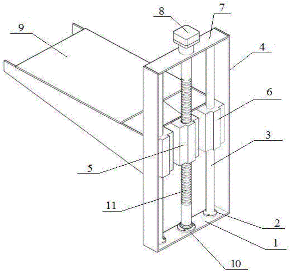
[0018] like figure 1 The described lifting device for a stage of a color 3D printer comprises a stage 9, a base plate 1, a support plate 4 symmetrically installed at both ends of the base plate 1, and a mounting frame 7 installed at the upper ends of the two support plates 4, the The middle part of the bottom plate 1 is provided with a bearing seat 10, and two mounting seats 2 are symmetrically arranged on the bottom plate 1 on both sides of the bearing seat 10, and the lower ends of the two support plates 4 are symmetrically installed on both ends of the bottom plate 1. A motor 8 is fixedly installed on the frame 7, and a moving screw 11 is installed in rotation on the bearing seat 10. The moving screw 11 passes through the mounting frame 7 and is connected to the axis of the motor 8. A moving nut is installed on the moving screw 11. 5. Two limit sliders 3 are symmetrically installed on the bottom plate 1 located on both sides of the moving screw 11. The lower end of the limi...
PUM
 Abstract
Description
Claims
Application Information