Breaker clutch mechanism

A clutch mechanism and circuit breaker technology, which is applied to the protection switch operation/release mechanism, circuit, and parts of the protection switch, etc., can solve the problems of complex structure and poor reliability of the clutch mechanism, and achieve simple manufacturing process and low production cost. , Effort-saving effect of shifting the clutch parts

Active Publication Date: 2015-04-29
ZHEJIANG TENGEN ELECTRIC
View PDF5 Cites 2 Cited by
  • Summary
  • Abstract
  • Description
  • Claims
  • Application Information

AI Technical Summary

Problems solved by technology

[0004] For this reason, the technical problem to be solved by the present invention lies in the problem that the clutch mechanism of the existing circuit breaker has a complex structure and poor reliability of action, and further provides a clutch mechanism of a circuit breaker with a simple structure and high reliability of action.

Method used


Image

  • Breaker clutch mechanism
  • Breaker clutch mechanism
  • Breaker clutch mechanism

Examples


Embodiment Construction

[0027] In the following, the present invention will be further described by using the following embodiments in conjunction with the accompanying drawings.

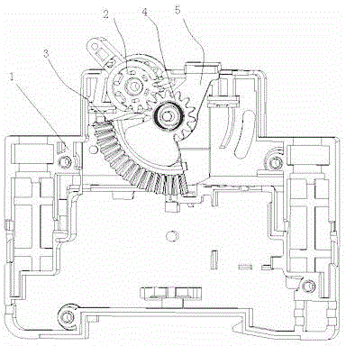
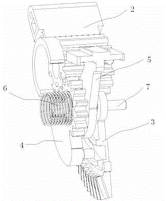
[0028] Such as figure 1 , figure 2 It is a clutch mechanism for a circuit breaker of the present invention, which includes a driving wheel 3 and a driven wheel 4 that cooperate with each other to realize linkage. The driving wheel 3 is driven to rotate by a driving motor, and the driven wheel 4 is connected to the handle 2 through a transmission mechanism A clutch 5 is provided between the driving wheel 3 and the driven wheel 4, and the clutch 5 drives the driven wheel 4 to be connected or separated from the driving wheel 3. The driving wheel 3 and the driven wheel 4 And the clutch parts 5 are sheathed on the rotating shaft 7 fixed on the housing 1 respectively.

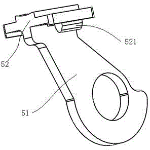
[0029] The above-mentioned clutch part 5 of the present invention, the driving wheel 3 and the driven wheel 4 are all sleeved on a rotating shaft 7, and the c...


PUM


Abstract

The invention discloses a breaker clutch mechanism and belongs to the design and production field of breakers. The breaker clutch mechanism comprises a driving wheel (3) and a driven wheel (4) which are matched and linked with each other. The driving wheel (3) is driven by a drive motor to rotate. The driven wheel (4) is connected with a handle (2) through a drive mechanism. A clutch member (5) is arranged between the driving wheel (3) and the driven wheel (4) and drives the driven wheel (4) to be separated from or connected with the driving wheel (3). The driving wheel (3), the driven wheel (4) and the clutch member (5) sleeve a rotating shaft (7) fixed on a shell (1). The use of the breaker clutch mechanism solves the problem that the conventional clutch mechanism is complicated in structure and poor in service reliability.

Description

technical field [0001] The invention belongs to the field of design and manufacture of circuit breakers, in particular to a clutch mechanism for circuit breakers. Background technique [0002] A circuit breaker refers to a switching device that can close, carry and break current under normal circuit conditions and can close, carry and break current under abnormal circuit conditions within a specified time. Circuit breakers can be used to distribute electric energy, start asynchronous motors infrequently, protect power lines and motors, and automatically cut off the circuit when they are severely overloaded, short-circuited, or under-voltage. Its function is equivalent to a fuse-type switch. Combination with overheating and underheating relays, etc., and generally do not need to change parts after breaking the fault current; at present, it has been widely used. [0003] At present, during the automatic closing process of the circuit breaker, if the line suddenly loses power,...

Claims


Application Information

Patent Timeline
Patent Type & Authority Applications(China)
IPC IPC(8): H01H71/10
CPCH01H71/10H01H2071/109
Inventor 徐大胜李敏丁国辉汪泰宇陈广哲
Owner ZHEJIANG TENGEN ELECTRIC
Why Eureka
Try Eureka