Machines for driving lifts

A technology of elevators and brakes, which is applied in the field of electric mechanical devices, can solve problems such as laborious motor assembly, reduce wear and noise, and improve mechanical performance

Active Publication Date: 2017-06-27
MOTEURS LEROY SOMER
View PDF3 Cites 0 Cited by
  • Summary
  • Abstract
  • Description
  • Claims
  • Application Information

AI Technical Summary

Problems solved by technology

[0006] This imposes the effect of relatively small pulley diameters, laborious motor assembly, e.g. out of sight, difficulty in controlling the air gap and difficulty in manufacturing a rigid c

Method used


Image

  • Machines for driving lifts
  • Machines for driving lifts
  • Machines for driving lifts

Examples


Example Embodiment

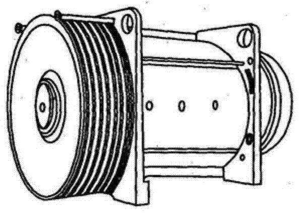
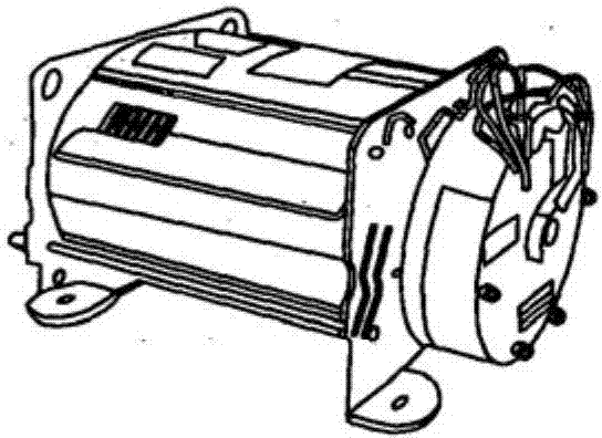
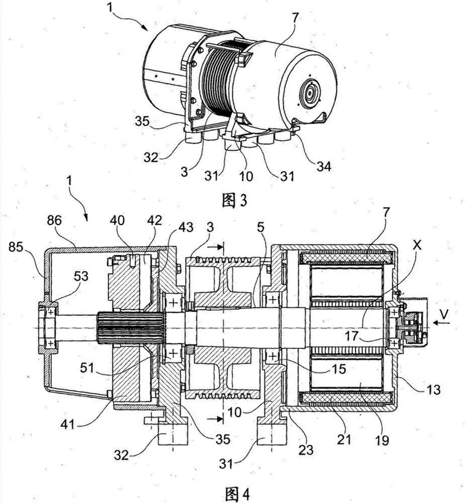
[0063] The mechanical device 1 according to the invention shown in Figures 3 to 5 comprises a pulley 3 mounted on a shaft 5 which rotates about a preferably horizontal axis of rotation X.

[0064] The pulley 3 may be mounted on the shaft 5 in any suitable known manner, for example, by a shrinking, conical taper fit or a spline and adapter.

[0065] The mechanical device 1 includes a motor 7 located on one side of the pulley 3. The motor 7 includes a first front support 10 and a rear support 13 respectively carrying a front rolling bearing 15 and a rear rolling bearing 17, and the first front support 10 supports the motor 7 The rolling bearing is, for example, a ball bearing.

[0066] The motor 7 further includes a rotor 19 and a stator 21, and the stator 21 is carried by a housing 23 extending between the first front support 10 and the rear support 13.

[0067] The housing 23 and the rear support 13 may be made in one piece as shown, or in the form of parts to be assembled, as shown i...


PUM


Abstract

An electrical machine for driving a pulley, including: a shaft whereon the pulley is mounted; a motor for driving the shaft; at least one brake; a first front bearing for supporting the motor, the first front bearing being arranged on one side of the pulley, carrying a front ball bearing and being supported by at least one damping element; and a second front bearing arranged on the opposite side, carrying at least one ball bearing and supported by at least one damping element. The machine does not contain a rigid connection between the first front bearing for supporting the motor and the second front bearing.

Description

technical field [0001] The invention relates to an electromechanical device, in particular for driving an elevator. Background technique [0002] An elevator drive mechanism includes pulleys mounted on a shaft driven by an electric motor, and one or more brakes that prevent rotation of the shaft when the motor is not operating. [0003] Many designs of elevator belt or cable driven mechanisms have been proposed. In general, the mechanical device must be as compact as possible in order to enable its installation in small spaces. [0004] In some mechanisms, such as figure 1 As shown in , the pulleys are outboard cantilever pulleys, meaning the motor is mounted on a rigid support with performance-enhancing rolling bearings and shafts. The brake is located close to the motor, which makes the brake sensitive to motor heat. Furthermore, since the motor is centrally located, it is difficult to ventilate. [0005] In other embodiments, such as figure 2 As shown, the pulley i...

Claims


Application Information

Patent Timeline
IPC IPC(8): B66B11/04
Inventor 伯努瓦·文森特帕斯卡尔·卡里奥帕斯卡尔·贝诺
Owner MOTEURS LEROY SOMER
Why Eureka
Try Eureka