Hydraulic device

A hydraulic device and hydraulic technology, applied in the direction of fluid pressure actuators, servo motors, servo motor components, etc., can solve the problems of high cost, complex structure, easy damage of hydraulic valves, etc., and achieve simple structure, low cost, and convenient control Effect

Active Publication Date: 2015-10-14
许昌思迪讴机械科技有限公司
View PDF5 Cites 0 Cited by
  • Summary
  • Abstract
  • Description
  • Claims
  • Application Information

AI Technical Summary

Problems solved by technology

[0002] In the prior art, there are many kinds of hydraulic devices, but they have the disadvantages of complex structure and high cost, which makes the hydraulic valve easy to damage, and the price is unacceptable to users

Method used


Image

  • Hydraulic device

Examples


Embodiment Construction

[0016] The present invention will be further described below in conjunction with the accompanying drawings.

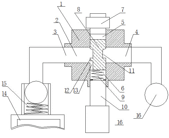
[0017] Such as figure 1 As shown, a hydraulic device is characterized in that it includes a hydraulic valve, the hydraulic valve has a housing 1, and a first channel 2 passing through the left and right is arranged on the housing, and the first channel has a left port 3 and a right port. There is a second channel 5 that penetrates up and down on the housing. The first channel and the second channel intersect to form a cavity with a "ten" structure. The second channel is a lower channel under the "ten" structure. Channel 6, there is an electromagnet 7 above the second channel, a spool 8 that can slide up and down along the second channel is arranged under the electromagnet, a first spring 9 supporting the spool is arranged below the spool, and a lower spring 9 is arranged below the second channel. Exit of channel 6;

[0018] In the middle of the spool is a thinning ne...


PUM


Abstract

The invention relates to a hydraulic device which comprises a hydraulic valve. The hydraulic valve is provided with a shell. The shell is provided with a first channel penetrating through the shell horizontally. The first channel is provided with a left opening and a right opening. The shell is provided with a second channel penetrating through the shell vertically. The first channel and the second channel intersect with each other to form a cavity of a cross structure. The portion, below the cross structure, of the second channel is provided with a lower channel. An electromagnet is arranged above the second channel. A valve element capable of sliding along the second channel vertically is arranged below the electromagnet. A first spring for supporting the valve element is arranged below the valve element. An outlet of the lower channel is formed below the second channel. The middle of the valve element is the neck portion which becomes thinner. A sealing ring matched with the lower portion of the second channel is arranged below the valve element. A side seam is arranged below the sealing ring. The hydraulic device has the advantages that whether the lower channel and the first channel are communicated with each other or not can be controlled by controlling the electromagnet, and the hydraulic device further has the advantages of being simple in structure and low in cost.

Description

technical field [0001] The present invention relates to a hydraulic device, which is widely used in some machine equipment, such as bending machines, cutting machines and the like. Background technique [0002] In the prior art, there are many kinds of hydraulic devices, but they have the disadvantages of complex structure and high cost, which makes the hydraulic valve easy to damage, and the price is unacceptable to users. Contents of the invention [0003] The object of the present invention is to provide a hydraulic device with simple structure and low cost to solve the above disadvantages. [0004] The technical solution of the present invention is achieved in the following way: a hydraulic device, characterized in that it includes a hydraulic valve, the hydraulic valve has a housing, and on the housing there is a first passage through the left and right, the first passage has The left port and the right port have a second channel that runs through up and down on the ...

Claims


Application Information

Patent Timeline
Patent Type & Authority Applications(China)
IPC IPC(8): F15B13/044F15B11/00
CPCF15B11/00F15B13/044
Inventor 马光辉
Owner 许昌思迪讴机械科技有限公司
Why Eureka
Try Eureka