Two-stage double-spring direct relief valve and control method thereof

A direct-acting relief valve, double-spring technology, used in safety valves, balance valves, valve devices, etc., can solve problems such as wear and noise

Inactive Publication Date: 2015-11-25
FUZHOU UNIV
View PDF8 Cites 10 Cited by
  • Summary
  • Abstract
  • Description
  • Claims
  • Application Information

AI Technical Summary

Problems solved by technology

[0005] Therefore, the failure of the overflow valve is largely caused by the collision between the valve core and the valve seat. The collision will cause noise and also cause wear on the relative moving parts.

Method used


Image

  • Two-stage double-spring direct relief valve and control method thereof
  • Two-stage double-spring direct relief valve and control method thereof

Examples


Embodiment Construction

[0032] The present invention will be further described below in conjunction with the accompanying drawings and specific embodiments.

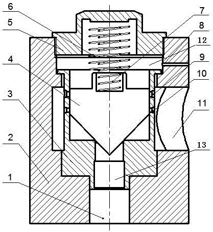
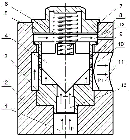
[0033] Such as Figure 1-2 As shown, the embodiment of the present invention provides a two-stage double-spring direct-acting overflow valve, which includes a valve body 2, and a stepped accommodation cavity is provided in the middle of the valve body 2 along the longitudinal direction. There is a valve seat 3 which slides in cooperation with the accommodation chamber, the bottom surface of the valve seat 3 and the bottom opening of the valve body 2 form an oil inlet 1; Oil port 1, the oil inlet 1 extends inward to one side of the valve seat 3; a valve core 4 is provided in a sliding sleeve inside the valve seat 3, and the width of the upper part of the valve core 4 is smaller than that of the middle part of the valve core 4 The lower part of the spool 4 is conical, and the lower part of the spool 4 is connected with the conical hole 13 that r...


PUM


Abstract

The invention relates to a two-stage double-spring direct relief valve and a control method thereof. The two-stage double-spring direct relief valve comprises a valve body internally provided with an oil inlet and an oil outlet. A valve seat is sleeved with the valve body in a sliding manner. A valve element is sleeved with the valve seat in a sliding manner. The width of the upper portion of the valve element is smaller than that of the middle of the valve element. The lower portion of the valve element is conical, the conical lower portion of the valve element is in matching connection with a conical hole penetrating the bottom of the valve seat, and the conical hole is communicated with the oil inlet. A second damping hole and a first damping hole are sequentially and vertically formed in the two sides of the valve seat in a transverse penetrating manner respectively. A pressure adjusting screw is further included and arranged at the top end of the valve body and is in threaded fit with the inner side of the valve body. An outer pressure adjusting spring is arranged in a rod portion of the pressure adjusting screw in the length direction, an inner pressure adjusting spring is coaxially sleeved with the outer pressure adjusting spring, and one end of the inner pressure adjusting spring is connected with the top end of the valve element. The two-stage double-spring direct relief valve has the beneficial effects that collisions between the valve body and the valve seat can be reduced, and the service life of the valve can be prolonged.

Description

technical field [0001] The invention relates to the field of engineering machinery, in particular to a two-stage double-spring direct-acting overflow valve suitable for hydraulic equipment of engineering machinery such as loaders. Background technique [0002] As one of the main types of construction machinery, loaders have the advantages of flexible and convenient operation, powerful functions and diverse varieties. They are indispensable equipment in mining, road transportation, national defense and urban construction. The hydraulic system is one of the core systems of the loader, which can realize the control of various actions of the whole machine and play a decisive role in the actual working performance of the loader. [0003] With the development of the global industry, the application field and scope of hydraulic technology are constantly expanding. While the hydraulic system of the loader is constantly developing in the direction of high pressure, large flow, and hi...

Claims


Application Information

Patent Timeline
Patent Type & Authority Applications(China)
IPC IPC(8): F15B13/02
CPCF15B13/023F16K17/044
Inventor 陈淑梅陈炳兴孙文毅许德坤章志超苏龙山
Owner FUZHOU UNIV
Why Eureka
Try Eureka