A Specimen Fixture with Self-Adaptive Contact of Frictional Surface

A friction surface, self-adaptive technology, used in measuring devices, instruments, scientific instruments, etc., can solve the problem of friction pairs not being in good contact, and achieve the effect of uniform force and avoiding cumbersome processes.

Active Publication Date: 2018-01-23
CHINA UNIV OF MINING & TECH
View PDF15 Cites 0 Cited by
  • Summary
  • Abstract
  • Description
  • Claims
  • Application Information

AI Technical Summary

Problems solved by technology

[0006] Technical problem: The purpose of the present invention is to solve the problem that the friction pair cannot be in good contact in the prior art, and to provide a specimen fixture with a compact and reasonable structure and a good clamping effect for self-adaptive contact of the friction surface

Method used


Image

  • A Specimen Fixture with Self-Adaptive Contact of Frictional Surface
  • A Specimen Fixture with Self-Adaptive Contact of Frictional Surface
  • A Specimen Fixture with Self-Adaptive Contact of Frictional Surface

Examples


Embodiment 1

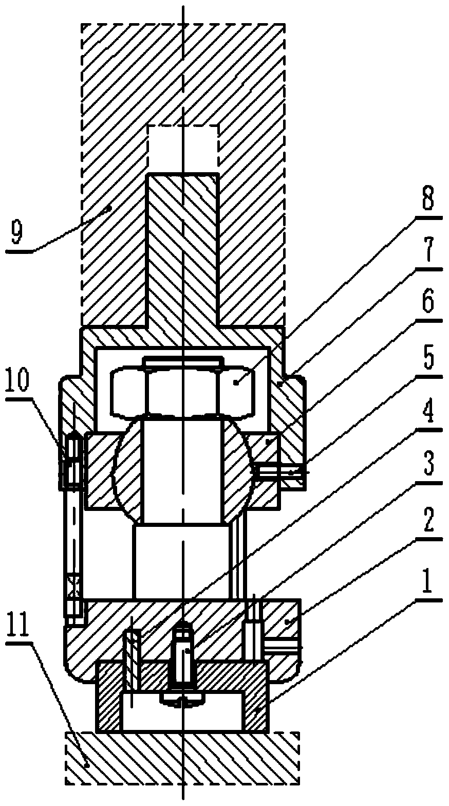
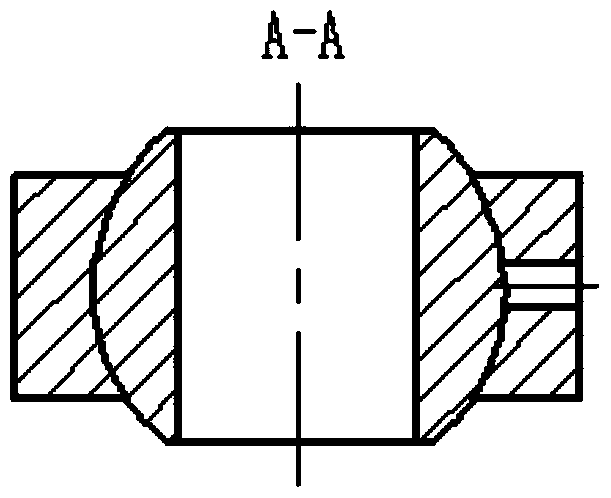
[0026] Embodiment 1, as shown in Fig. 1 (a), the specimen fixture of frictional surface self-adaptive contact is mainly composed of ring specimen 1, clamping piece 2, slotted spherical cylindrical head screw 3, positioning pin 4, slotted cone end Set screws 5, centripetal joint bearings 6, cup-type fixing parts 7, hexagonal nuts 8, and studs 10; On the ball bearing 6, the outer wall of the cup-type fixing part 7 is provided with an upper slotted taper end set screw 5 fixed together with the radial joint ball bearing 6, and the end surface of the cup-type fixing part 7 is provided with abutment The stud 10 on the opposite end surface of the clamping part 2;

[0027] The clamping part 2 is T-shaped, the T-shaped head is a disk, the T-shaped rear part is a stepped shaft that is fitted with a radial joint ball bearing 6, and the tail of the stepped shaft is threaded to fix the radial joint ball bearing 6 8 hexagonal nuts, the shaftless end of the clamping piece 2 has an inner gro...

Embodiment 2

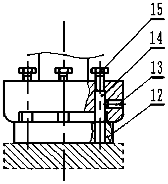
[0031] Embodiment 2 is basically the same as Embodiment 1, and the similarities are omitted. The difference is as shown in Figure 1(b), a spacer 12 is provided under the inner groove at the shaftless end of the head disc of the clamping part 2, and a pad 12 is provided on the spacer 12 to match the circular shape of the head of the clamping part 2. The three through holes corresponding to the three bolt holes on the plate are provided with a pin test piece 14 that enters the pad 12 from the bolt hole, and the top of the pin test piece 14 is provided with a fixing bolt 15, and the pin test piece 14 A set screw 13 with a lower slotted taper end passing through the side wall of the head disc of the clamping part 2 is provided on the side. According to the needs of the experiment, the test piece under the pad 12 can be a plate test piece or a pin test piece, and the contact of the pin test piece 14 with the plate test piece or the pin test piece can realize the pin-disc experiment...


PUM


Abstract

The invention relates to a test piece fixture with self-adaptive contact of friction surface, which belongs to the field of test piece fixture design of tribological friction and wear testing machine. The device mainly includes a clamping piece, a radial joint ball bearing and a cup-type fixing piece; the ball bearing includes an inner ring and an outer ring. The fixed screw is connected to prevent the ball bearing from loosening; the cup-type fixing part and the clamping part are connected by three studs evenly distributed along the circumferential direction; both the ring test piece and the pin test piece can be installed on the clamping part. The specimen fixture has reasonable design, compact structure, and good clamping effect. Through the cooperation of joint ball bearings, positioning bolts and pins, the friction surfaces of the upper specimen and the lower specimen can be ensured to be in adaptive contact, and the force is uniform. Instead of the single-pin mode, it makes up for the limitations of the single-pin mode, and can realize various friction and wear tests of ring-disc, ring-ring, pin-disk, and pin-ring without changing the fixture.

Description

technical field [0001] The invention relates to the design field of a test piece fixture of a tribological friction and wear testing machine, in particular to a test piece fixture for self-adaptive contact of a friction surface. Background technique [0002] At present, the friction and wear testing machine is mainly used for ring-disc, ring-ring, pin-disc, pin-ring friction and wear tests. However, most testing machines are required to replace different specimen fixtures according to different types of tests. There are disadvantages such as cumbersome operation and complicated replacement. [0003] At present, pin-disk or pin-ring friction and wear testing machines are generally single-pin mode, because of the particularity of single pin, in order to ensure that the pin-disk test The test bench needs to be adjusted before testing on the wear testing machine. In the process of adjusting the position, it is generally judged whether the position is suitable according to the n...

Claims


Application Information

Patent Timeline
Patent Type & Authority Patents(China)
IPC IPC(8): G01N3/04
Inventor 朱华丁丛孙国栋周元凯左雪
Owner CHINA UNIV OF MINING & TECH
Why Eureka
Try Eureka