Tubular product bending method

A pipe and bending technology, which is applied in the field of pipe bending, can solve the problems of increasing mandrel manufacturing and use costs, high mold design and manufacturing costs, and difficulty in controlling pipe wrinkling, etc., to achieve reduced scratches, low use and maintenance costs, The effect of suppressing the possibility of wrinkling

Active Publication Date: 2015-02-04
AVIC BEIJING AERONAUTICAL MFG TECH RES INST
View PDF7 Cites 0 Cited by
  • Summary
  • Abstract
  • Description
  • Claims
  • Application Information

AI Technical Summary

Problems solved by technology

However, the maximum rotation range of the ball head of the existing metal mandrel can only guarantee a bending radius greater than 1.2 times the pipe diameter
In addition, the reduction of the bending radius of the pipe will lead to an increasing possibility of wrinkling of the pipe. Therefore, it is necessary to reduce the gap between the metal mandrel and the pipe and improve the matching accuracy to reduce the possibility of wrinkling of the pipe. Increase the cost of mold processing and manufacturing
[0004] 2. During the pipe bending process, the phenomenon of uneven contact between the core mold and the inner wall of the pipe is prominent, the inner cavity of the pipe is severely scratched, and it is difficult to control the wrinkling of the pipe and the forming quality is difficult to control
[0005] 3. Due to the difference in the geometric dimensions of the pipes, it is necessary to make mandrels according to the inner diameter of the pipes, and the size of different batches of pipes of the same specification will change. Therefore, it is necessary to order multiple sets of mandrels. Reduced the manufacturing and use costs of the mandrel

Method used


Image

  • Tubular product bending method
  • Tubular product bending method
  • Tubular product bending method

Examples


Embodiment approach

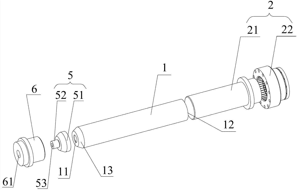
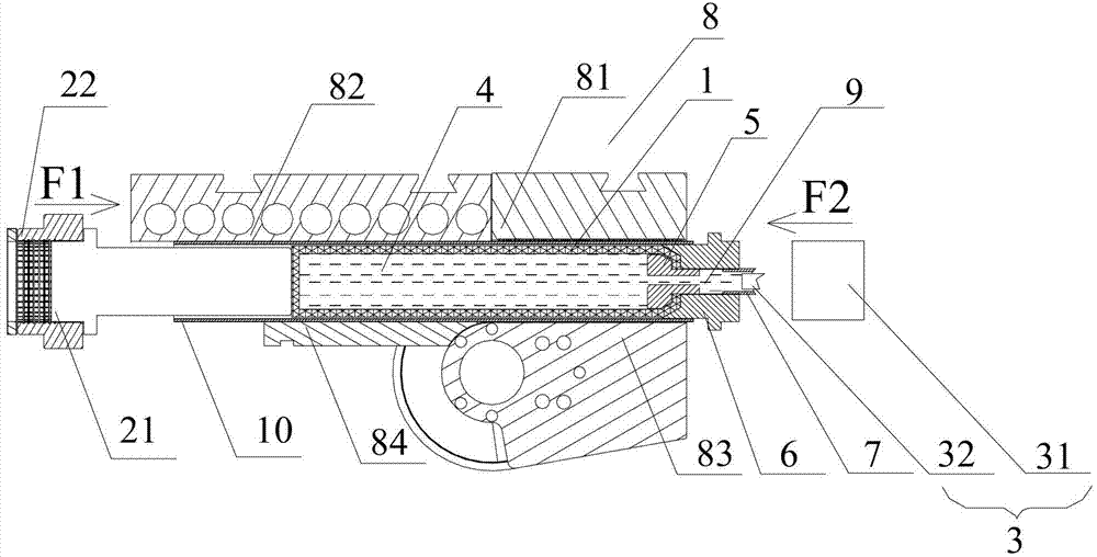
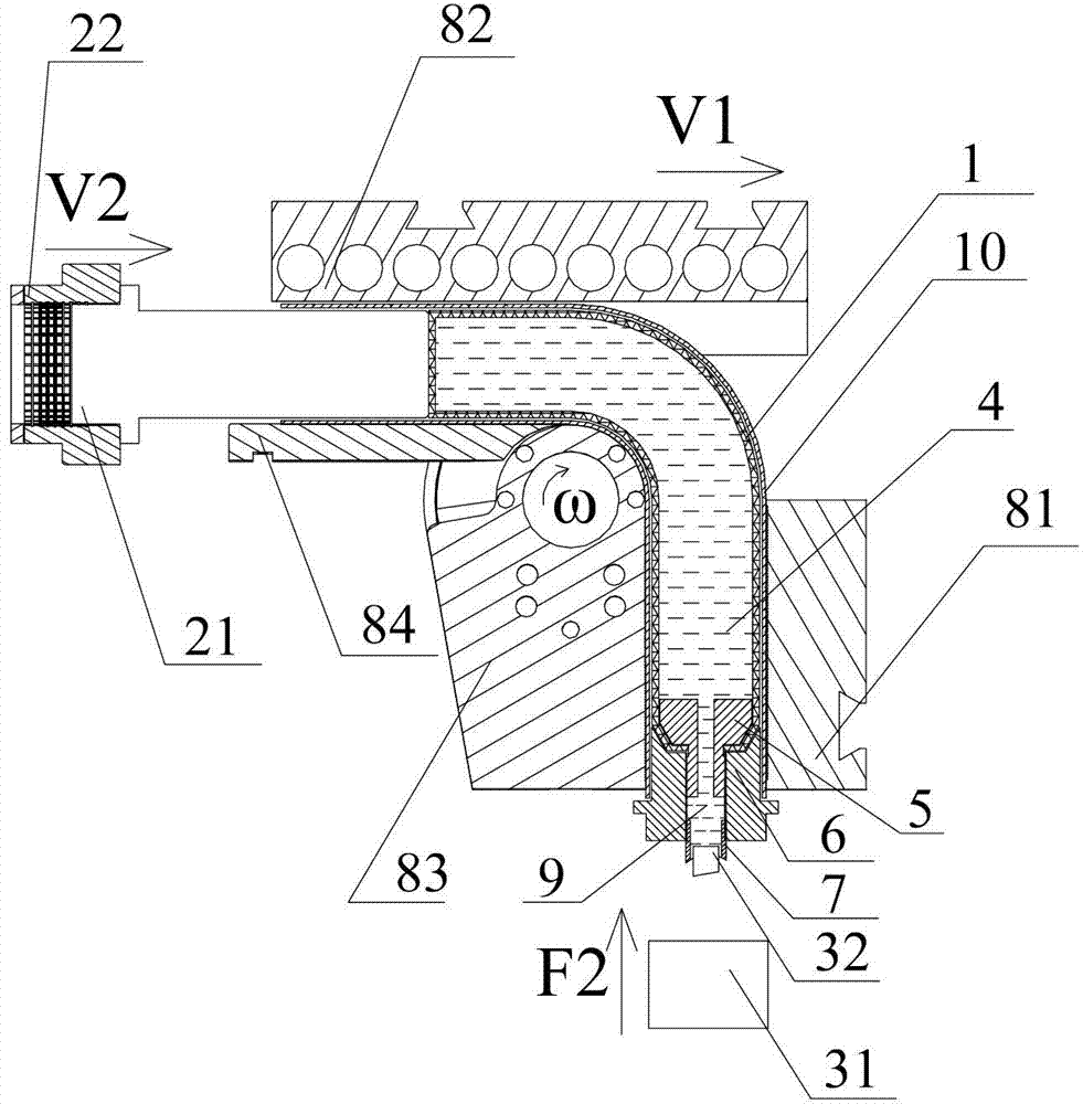
[0041] Step 1: Customize a cylindrical rubber bag 1 according to the inner diameter of the pipe 10 (for example, the inner diameter is greater than or equal to 20 mm). There is a certain gap between the outer wall of the rubber bag 1 and the inner wall of the pipe 10, and the diameter of the rubber bag 1 is 2 mm to 3 mm smaller than the inner diameter of the pipe 10. The rubber bag 1 has a thickness of 3 mm to 5 mm, and the head of the rubber bag 1 is in the shape of a truncated cone, and the end face of the head is perforated to form a through hole 11 through the inner cavity of the rubber bag 1; the cone angle of the head of the rubber bag 1 is 10°- 30°, the height of the round platform is 20mm-50mm, the end face of the head is perforated, and the aperture is 5mm-50mm smaller than the diameter of the end face; in this embodiment, according to the inner diameter of the pipe 10 of 68mm, a cylindrical rubber bag 1 is customized, and the diameter of the rubber bag 1 is 66mm. The ...


PUM

PropertyMeasurementUnit
angleaaaaaaaaaa
heightaaaaaaaaaa

Abstract

The invention discloses a tubular product bending internal pressing supporting device and a tubular product bending method. The tubular product bending material pressing supporting device comprises a hollow cylindrical rubber bag, an ejecting mechanism and an infusion and pressurization mechanism, wherein a through hole is formed in one end of the rubber bag and the other end of the rubber bag is sealed, the ejecting mechanism abuts against the outer side of the sealed end of the rubber bag, and the infusion and pressurization mechanism is arranged at the end, with the through hole, of the rubber bag. The infusion and pressurization mechanism comprises a pressurization cylinder provided with a piston rod and a sealing component, the sealing component is clamped at the side, with the through hole, of the rubber bag in a sealing mode, a liquid flowing channel is arranged at the center of the sealing component, the pressurization cylinder is connected with the liquid flowing channel in a sealing mode through a cylindrical connecting body, and the piston rod stretches into the liquid flowing channel through the cylindrical connecting body; liquid medium in the rubber bag pushes a sealing plug to pressurize through the piston rod of the pressurization cylinder to drive the rubber bag to expand in the radial direction. The tubular product bending internal pressing supporting device is matched with the inner wall of a tubular product in a self-adaptation mode, contact is even, the inner cavity of the tubular product is prevented from being scratched and wrinkling, and manufacturing and using cost can be greatly reduced.

Description

technical field [0001] The invention relates to the field of mechanical processing, in particular to a pipe bending method. Background technique [0002] As we all know, the bending and forming of pipes requires the synergy and strict cooperation of multiple molds. During the bending forming process, the clamp block drives the pipe and the bending die to rotate synchronously. Under the action of the clamp block tension, the pipe slides over the bending tangent point, and bends and deforms under the bending moment of the bending plane and contacts the bending die, thus The predetermined bending radius of the pipe is formed, and the bending moment of the pipe will be generated by the resultant force of the pulling force of the clamp on the pipe and the friction between the pipe molds. During the pipe bending process, in order to prevent the pipe from wrinkling and excessive flattening of the cross section, it is necessary to insert a metal mandrel with several ball heads in t...

Claims


Application Information

Patent Timeline
Patent Type & Authority Patents(China)
IPC IPC(8): B21D9/01B21D9/15B21D9/16
Inventor 闫晶吴为曾元松
Owner AVIC BEIJING AERONAUTICAL MFG TECH RES INST
Why Eureka
Try Eureka