Cover for locking elements of kitchen machines

A locking element, technology of kitchen machines for use in the direction of applications, kitchen appliances, home appliances

Active Publication Date: 2019-08-06
VORWERK & CO INTERHOLDING GMBH
View PDF6 Cites 0 Cited by
  • Summary
  • Abstract
  • Description
  • Claims
  • Application Information

AI Technical Summary

Problems solved by technology

[0004] Based on the prior art described above, the technical problem to be solved by the present invention is to protect the locking element and / or the connection area between the locking element and the kitchen machine from contamination

Method used


Image

  • Cover for locking elements of kitchen machines
  • Cover for locking elements of kitchen machines
  • Cover for locking elements of kitchen machines

Examples


Embodiment Construction

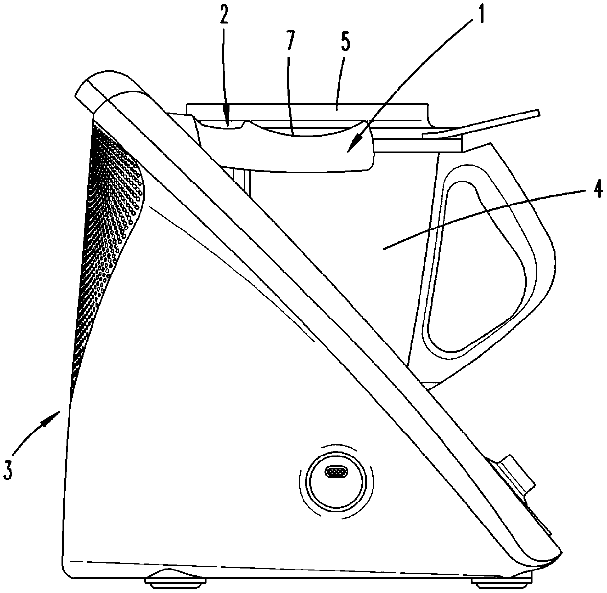
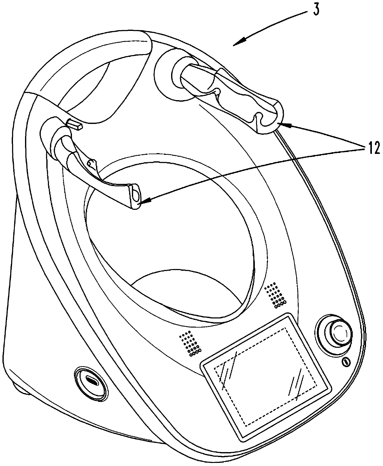
[0027] first combine figure 1 and figure 2 An electrically driven kitchen appliance 3 is shown and described. The kitchen appliance essentially has an operating panel with preferably a plurality of controls and / or keys and preferably with a display for displaying parameters to be adjusted via the controls and / or keys. Furthermore, the kitchen appliance 3 has a container receptacle.

[0028] A container 4 in the form of a stirring container is installed in the container receptacle. The container 4 is preferably designed to be substantially rotationally symmetrical. A stirrer can be arranged in the bottom region of the container 4 . The stirrer is coupled to a stirrer drive provided in the kitchen machine 3 when the container 4 is in the corresponding position in the container receptacle of the kitchen machine 3 . The power supply to the electric motor forming the stirrer drive as well as the further heating device, which is preferably arranged on the bottom side of the co...


PUM


Abstract

The invention relates to a locking element (2), particularly a locking roller, for lockingbetween a vessel (4) of a kitchen appliance (3) and a cover (5), wherein the locking element (2) is provided with a base body (12) and a cover element (1) only partially covering the base body (1), the cover element (1) at least partially is provided with an edge region (7) of a folded edge facing the base body (12), and a the cover element (1) is arranged on the base body (12) by means of the edge region in a preloaded manner.

Description

technical field [0001] The invention relates to a locking element, in particular a locking roller, for locking a container and a lid of a kitchen machine, and to a kitchen machine having a container, a cover which at least partially closes the container and at least a a locking element. Background technique [0002] It is known to close a container of a kitchen appliance with a lid and to lock it by means of a locking element. Kitchen machines of this type are, for example, cooking mixers, which have a mixer associated with the container and a heating device. In this connection, reference may be made, for example, to document EP 2 698 088 A1. The kitchen machine described there is an electrically driven kitchen machine with a stirring vessel and a lid for the stirring vessel, wherein the lid can be locked in a closed position relative to the stirring vessel, and wherein the stirring vessel has a container A bottom and a container wall extending upwardly from the container...

Claims


Application Information

Patent Timeline
Patent Type & Authority Patents(China)
IPC IPC(8): A47J43/07
CPCA47J43/0761
Inventor F.斯塔福林格E.舍恩劳T.格莱泽
Owner VORWERK & CO INTERHOLDING GMBH
Why Eureka
Try Eureka