AI technical title is built by Patsnap AI team. It summarizes the technical point description of the patent document.
A high-voltage switchgear, multi-functional technology, applied in the direction of panel/switch station circuit device, substation/switch layout details, substation/switch device cooling/ventilation, etc., can solve the problem of increasing workload and working intensity, failure of normal power supply, To avoid problems such as property loss, to ensure continuous and stable operation, to facilitate the storage and discharge of power components, and to improve the service life
Inactive Publication Date: 2017-03-22
QIXIA POWER SUPPLY CO STATE GRID SHANDONG ELECTRIC POWER CO
View PDF5 Cites 0 Cited by
Summary
Abstract
Description
Claims
Application Information
AI Technical Summary
This helps you quickly interpret patents by identifying the three key elements:
Problems solved by technology
Method used
Benefits of technology
Problems solved by technology
[0002] The current production enterprises and power supply management need to use a large number of power distribution cabinets or control boxes to place various control switches, motors, generators or other control equipment. Some power distribution cabinets have complex structures and unreasonable placement. The line will be short-circuited due to messiness, resulting in abnormal power supply and serious property loss
Moreover, the functions of the existing high-voltage switchgear are relatively single, which cannot meet the needs of use, and the installation is complicated, thereby reducing the service life of various control switches, motors, generators or other control equipment, and increasing the workload and intensity.
Method used
Image
Click on the blue label to locate the original text in one second.
Reading with bidirectional positioning of images and text.
Examples
Embodiment Construction
[0018] The invention provides a multi-functional high-voltage switchgear, the main function of which is to provide a high-voltage switchgear with various functions to meet the needs of use. The high-voltage switchgear of the present invention has multiple functions, is convenient to use, is convenient to install and disassemble, and is convenient to hold and discharge power components. It does not need to be installed, greatly reduces the workload, thereby improving the service life, and at the same time has the function of temperature control, ensuring that the power components continuous and stable operation.
[0019] In order to better understand the above-mentioned technical solution, the above-mentioned technical solution will be described in detail below in conjunction with the accompanying drawings and specific implementation methods.
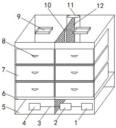
[0020] see Figure 1-4 As shown, a multifunctional high-voltage switch cabinet includes a cabinet body 5, and also includes a first cab...
PUM
Abstract
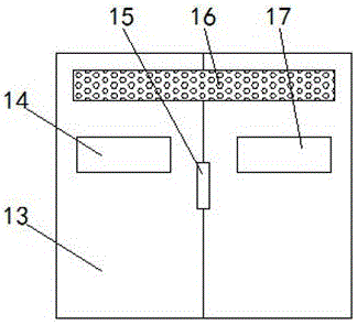
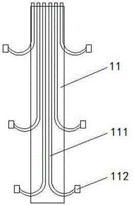
The invention discloses a multifunctional high-voltage switch cabinet. The multifunctional high-voltage switch cabinet comprises a cabinet body and further comprises a first cable channel, a cable monitoring device, a cable tube, a second cable channel, a partition plate, drawers, first handles, an insulation box, a notch, a long cylinder, a grid mesh, a back plate, an observation window, a second handle, ventilation holes, a display screen, fans, a switch controller, a controller, a temperature sensor, a cable wire and a plug, wherein the partition plate is arranged at the lower part of the cabinet body; the cable monitoring device is arranged in the cabinet body at the lower part of the partition plate; the cable monitoring device is connected with the first cable channel and the second cable channel through the cable tube; two fans are also arranged at the lower part of the cabinet body; the fans are successively connected with the switch controller, the controller and the temperature sensor through a circuit; the vertical grid mesh is arranged at the middle part of the cabinet body; the drawers with the first handles are respectively arranged on the cabinet body on two sides of the grid mesh. The multifunctional high-voltage switch cabinet has the advantages of reasonable design, convenience in use, various functions and high practicability.
Description
technical field [0001] The invention relates to the technical field of electric equipment, in particular to a multifunctional high-voltage switchgear. Background technique [0002] The current production enterprises and power supply management need to use a large number of power distribution cabinets or control boxes to place various control switches, motors, generators or other control equipment. Some power distribution cabinets have complex structures and unreasonable placement. The lines will be short-circuited due to messiness, resulting in abnormal power supply and serious property losses. Moreover, the existing high-voltage switchgear has relatively simple functions, cannot meet the use requirements, and is complicated to install, thereby reducing the service life of various control switches, motors, generators or other control equipment, and increasing the workload and intensity. Contents of the invention [0003] The invention provides a multi-functional high-volt...
Claims
Application Information
Patent Timeline
Application Date:The date an application was filed.
Publication Date:The date a patent or application was officially published.
First Publication Date:The earliest publication date of a patent with the same application number.
Issue Date:Publication date of the patent grant document.
PCT Entry Date:The Entry date of PCT National Phase.
Estimated Expiry Date:The statutory expiry date of a patent right according to the Patent Law, and it is the longest term of protection that the patent right can achieve without the termination of the patent right due to other reasons(Term extension factor has been taken into account ).
Invalid Date:Actual expiry date is based on effective date or publication date of legal transaction data of invalid patent.

