Automobile headlamp optical lens support structure

A technology of lens bracket and light optics, which is applied in the field of auto parts, can solve problems such as assembly difficulties, car driving danger, and headlight damage, and achieve the effect of stable bracket structure and firm fixation

Active Publication Date: 2016-05-11
GUANGZHOU DINGLI AUTOMOBILE AIR CONDITIONING
View PDF6 Cites 3 Cited by
  • Summary
  • Abstract
  • Description
  • Claims
  • Application Information

AI Technical Summary

Problems solved by technology

[0002] Existing car headlights are used to install the bracket of the optical lens, which is generally made into a whole ring, and a slot is arranged in the ring, and then the optical lens is forcibly snapped into the slot of the overall ring bracket. The lens can be fixed, but on the one hand, since the assembly is an integral snap-in assembly, when considering the problem of assembly fastening, the diameter of the integral ring bracket and the slot cannot be made too small, because too small will On the other hand, due to the overall snap-in assembly, rigid metal materials cannot be used to make the bracket ring, otherwise it will not fit in, so the only way to make the bracket ring is to use hard plastic materials, such as ABS plastic or PC plastic, and the pla

Method used


Image

  • Automobile headlamp optical lens support structure
  • Automobile headlamp optical lens support structure
  • Automobile headlamp optical lens support structure

Examples


Embodiment Construction

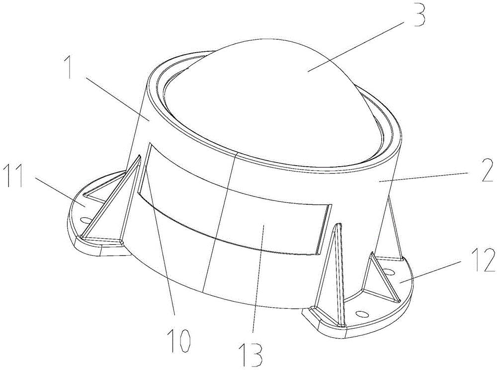
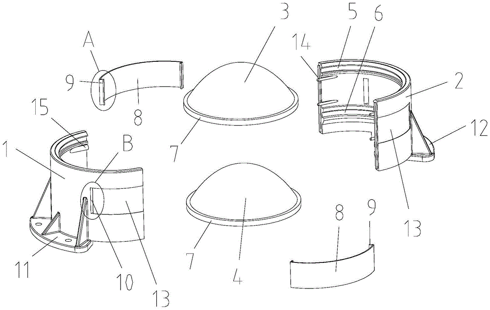
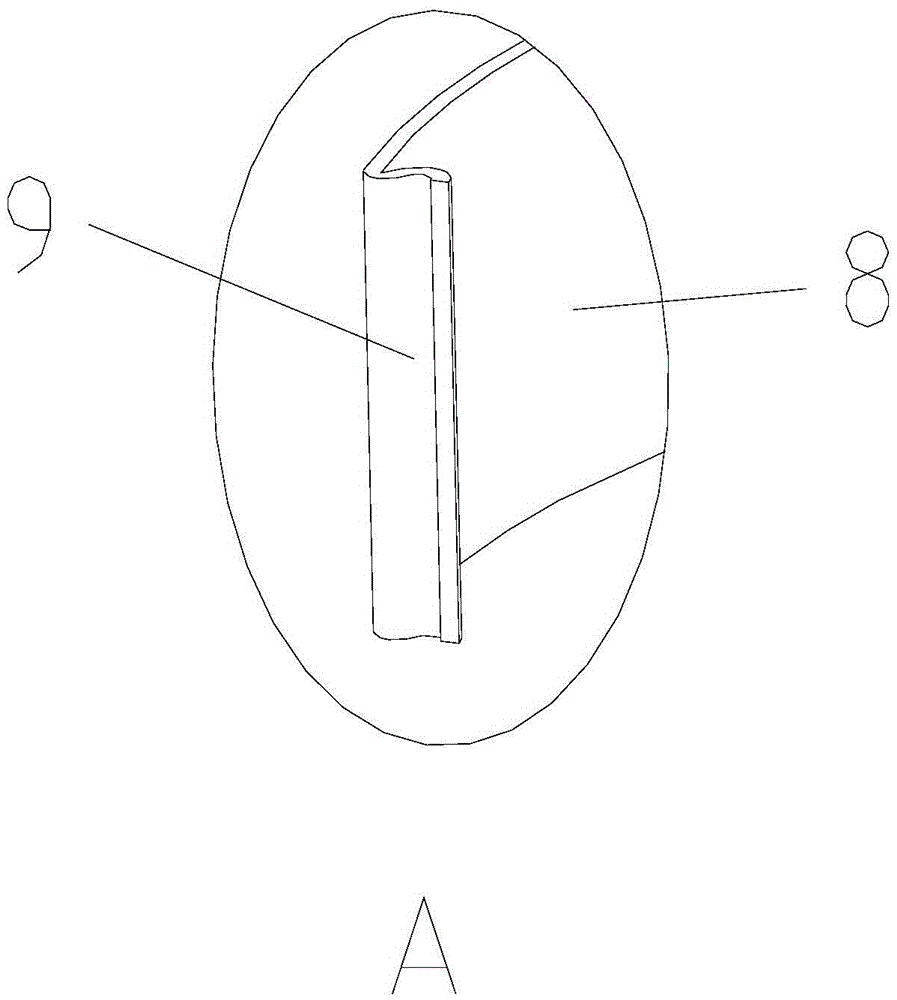
[0017] refer to Figure 1-Figure 5 , a kind of automobile headlight optical lens support structure of the present invention, comprises semicircular left and right support 1,2 and at least one lens 3 that is clamped at the inner side of left and right support, as Figure 5 As shown, the left and right brackets are relatively closed to form a ring, and the inner sides of the left and right brackets are respectively provided with semicircular lens slots 5 having the same number as the lenses, and the edges of the lenses are provided with snap rings 7 , the left and right brackets are oppositely provided with two arc-shaped metal clamping shrapnels 8 on the outside of the relative closure, and the metal clamping shrapnels are buckled by the barbs 9 at both ends to the hooks respectively located on the left and right brackets. In the slot 10, the rear ends of the left and right brackets are provided with left and right bracket fixing plates 11,12. The materials of the left and rig...


PUM


Abstract

The invention discloses an automobile headlamp optical lens support structure. The automobile headlamp optical lens support structure comprises a left semicircular support, a right semicircular support and at least one lens clamped on the inner side of the left support and the inner side of the right support. The left support and the right support are oppositely closed to form a ring shape. Semicircular lens clamping grooves are formed in the inner side of the left support and the inner side of the right support, wherein the number of the semicircular lens clamping grooves is equal to the number of the lenses. Clamping rings are arranged on the edges of the lenses. Two arc metal clamping elastic pieces are oppositely arranged on the outer side of the oppositely-closed position of the left support and the right support and clamped in a hook groove in the left support and a hook groove in the right support through barbs at the two ends in a buckled manner. A left support fixing plate and a right support fixing plate are arranged at the rear end of the left support and the rear end of the right support. After the circle is formed through closing of the semicircular front lens clamping grooves and the semicircular rear lens clamping grooves, the circle is in interference fit with the clamping ring on the edge of the front lens and the clamping ring on the edge of the rear lens. According to the automobile headlamp optical lens support structure, the lenses are fixed more firmly, lens disengaging due to vibration or thermal expansion and cold contraction can be prevented, the lenses cannot fall out of the left support or the right support at all, and the overall support structure is more stable and safer.

Description

technical field [0001] The invention relates to spare parts of automobiles, in particular to an automobile headlight optical lens support structure. Background technique [0002] Existing car headlights are used to install the bracket of the optical lens, which is generally made into a whole ring, and a slot is arranged in the ring, and then the optical lens is forcibly snapped into the slot of the overall ring bracket. The lens can be fixed, but on the one hand, since the assembly is an integral snap-in assembly, when considering the problem of assembly fastening, the diameter of the integral ring bracket and the slot cannot be made too small, because too small will On the other hand, due to the overall snap-in assembly, rigid metal materials cannot be used to make the bracket ring, otherwise it will not fit in, so the only way to make the bracket ring is to use hard plastic materials, such as ABS plastic or PC plastic, and the plastic material itself expands with heat and...

Claims


Application Information

Patent Timeline
IPC IPC(8): F21V17/16F21W101/02F21W101/10F21W107/10
CPCF21V17/164F21W2102/00F21W2107/10
Inventor 戴汉铭陈贤渊
Owner GUANGZHOU DINGLI AUTOMOBILE AIR CONDITIONING
Why Eureka
Try Eureka