A loader brake pump

A brake pump and loader technology, applied in the field of brake pumps, can solve problems such as hidden dangers of vehicle braking, reduced braking effect, brake failure of the whole vehicle, etc., and achieve the effects of less accident, good braking effect and safe use.

Active Publication Date: 2018-04-20
莱州虎威机械科技有限公司
View PDF8 Cites 0 Cited by
  • Summary
  • Abstract
  • Description
  • Claims
  • Application Information

AI Technical Summary

Problems solved by technology

[0002] The parking brake of the existing loader adopts the central disc brake. The brake disc is fixed on the transmission shaft and operated mechanically. The brake device can only be used after the loader has stopped. It is easy to cause damage to the transmission shaft and axle; if the loader is too heavy or parked on a slope, it is easy to cause parking failure and accidents
In addition, once the handbrake mechanism or transmission shaft fails, the brakes will fail; when driving, if any components such as air pumps, pipelines, air storage tanks, brake valves, etc. fail, the brakes will fail, which is very prone to accidents
[0003] In addition, although the utility model patent CN 204488780 U of the applicant also discloses a loader brake pump, which improves the above-mentioned brake pump, the brake chamber of the brake pump is provided with two sets of pistons connected in series to form two outlets. If the outer casing of the brake chamber is damaged, the brakes of the whole vehicle will fail; in addition, the two sets of piston seals will be worn out, and the liquid in the two storage tanks will leak into each other, reducing the braking effect; and the brake pump There is a complex spring structure inside the brake chamber. During work, the spring is easy to get stuck, especially the first return spring is easy to get stuck and fails, resulting in brake failure, which brings great hidden dangers to vehicle braking.

Method used


Image

  • A loader brake pump
  • A loader brake pump
  • A loader brake pump

Examples


Embodiment Construction

[0052] The following will be described in detail in conjunction with the accompanying drawings and embodiments.

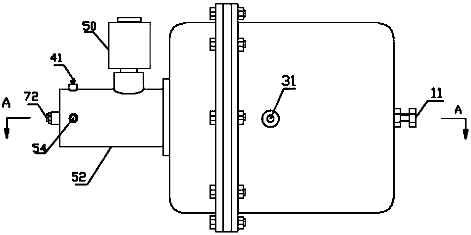
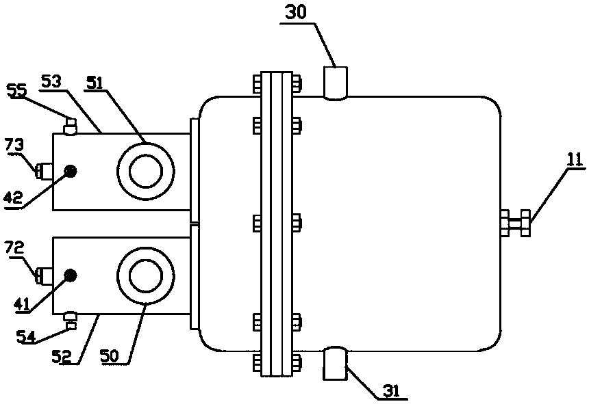
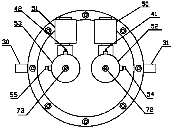
[0053] Such as Figure 1 to Figure 5 As shown, a brake pump for a loader of the present invention includes a brake pump housing. A brake chamber, a service brake chamber and a parking brake chamber are arranged in the brake pump housing. The service brake chamber is located on the left side of the parking brake chamber. , the brake chamber is located on the left side of the service brake chamber; the parking brake chamber is provided with a first piston 27, and a sealing ring 26 is provided between the first piston 27 and the inner wall of the parking brake chamber, and the first piston 27 is The brake chamber can move left and right. The first piston 27 divides the parking brake chamber into a parking brake air storage chamber 1 and a parking brake right chamber 32. The parking brake air storage chamber 1 is located in the right parking brake chamber 32. On the l...


PUM


Abstract

The invention discloses a brake pump of a loader. Two brake cavities, a traveling brake cavity and a stop brake cavity are formed in a brake pump shell; a first piston is arranged in the stop brake cavity; a first push rod is arranged on the left side of the first piston; a main spring is arranged on the right side of the first piston; a rubber bowl is arranged in the traveling brake cavity; the two braking cavities comprise a left brake cavity and a right brake cavity; a second piston is arranged in the left brake cavity; a first resetting spring is arranged on the left side of the second piston; a third piston is arranged in the right brake cavity; a second resetting spring is arranged on the left side of the third piston; a spring base is arranged on the left side of the rubber bowl; a second push rod and a third push rod are fixed on the left end face of the spring base; a first spring sleeves the second push rod; a second spring sleeves the third push rod; the second push rod corresponds to the second piston; the third push rod corresponds to the third piston; a first liquid storage tank is arranged above the left brake cavity; and a second liquid storage tank is arranged above the right brake cavity. The brake pump is good in brake effect and can be used safely and reliably.

Description

technical field [0001] The invention relates to a brake pump, in particular to a loader brake pump. Background technique [0002] The parking brake of the existing loader adopts the central disc brake. The brake disc is fixed on the transmission shaft and operated mechanically. The brake device can only be used after the loader has stopped. It is easy to cause damage to the drive shaft and axle; if the loader is too heavy or parked on a slope, it is easy to cause parking failure and accidents. In addition, once the handbrake mechanism or transmission shaft fails, the brakes will fail; when driving, if any components such as air pumps, pipelines, air storage tanks, brake valves, etc. fail, the brakes will fail, which is very prone to accidents. [0003] In addition, although the utility model patent CN 204488780 U of the applicant also discloses a loader brake pump, which improves the above-mentioned brake pump, the brake chamber of the brake pump is provided with two sets o...

Claims


Application Information

Patent Timeline
Patent Type & Authority Patents(China)
IPC IPC(8): F16D65/22F16D121/10F16D121/06
CPCF16D65/22F16D2121/06F16D2121/10
Inventor 聂瑞波
Owner 莱州虎威机械科技有限公司
Why Eureka
Try Eureka