A structure of a rope-driven mechanical arm rotary joint

A technology of rotating joints and robotic arms, applied in the field of robotics, can solve the problems of many wheel sets, heavy weight, inability to solve joint motion coupling and small driving range, and achieve the effect of precise control and convenient protection

Inactive Publication Date: 2017-10-20
SOUTH CHINA UNIV OF TECH
View PDF7 Cites 0 Cited by
  • Summary
  • Abstract
  • Description
  • Claims
  • Application Information

AI Technical Summary

Problems solved by technology

The existing method is to realize speed regulation and long-distance transmission of power. There are many wheel sets, complex mechanism, heavy weight, and it cannot solve the shortcomings of joint motion coupling and small driving range.

Method used


Image

  • A structure of a rope-driven mechanical arm rotary joint
  • A structure of a rope-driven mechanical arm rotary joint
  • A structure of a rope-driven mechanical arm rotary joint

Examples


Embodiment Construction

[0030] The specific implementation of the present invention will be further described in detail below in conjunction with the accompanying drawings, but the implementation of the present invention is not limited thereto.

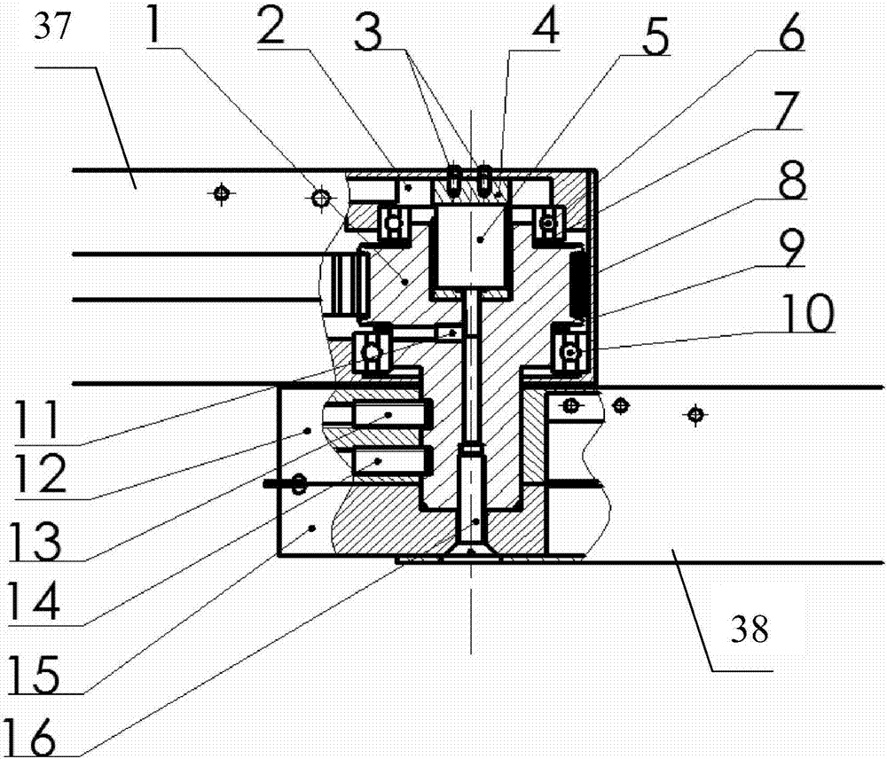
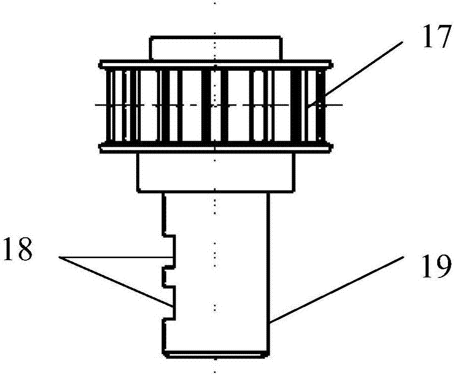
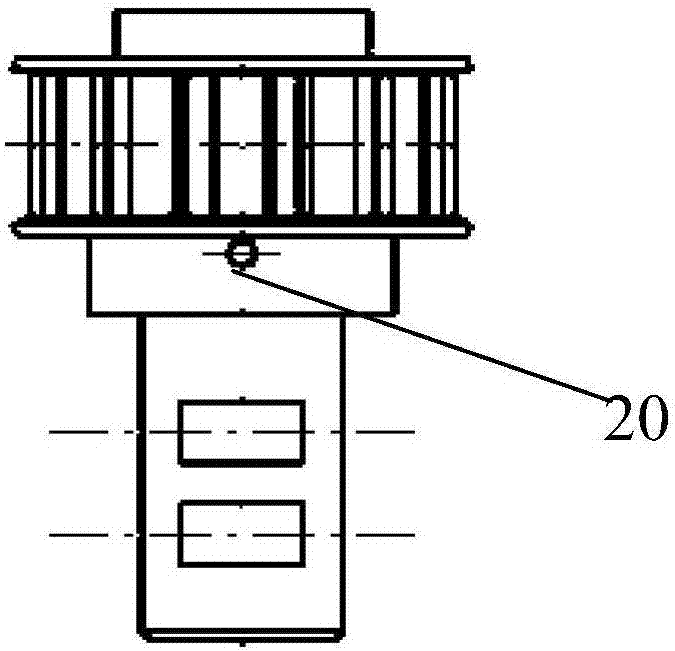
[0031] Such as Figure 1 to Figure 4As shown, a structure of a rope-driven mechanical arm rotary joint includes a synchronous belt wheel shaft 1, a synchronous belt 8, an angle sensor 5, an arm joint bearing end cover 2, a deep groove ball bearing 6, an angular contact ball bearing 10, and a connection hole and the mechanical arm connecting the steel wire rope through hole, the synchronous pulley shaft 1 includes a pulley end 17 and a shaft end 19 from top to bottom, along the axis of the synchronous pulley shaft 1, a sensor accommodation hole 21, a sensor output Shaft connection hole 22, cross countersunk screw internal thread hole 23, the inner ring of the deep groove ball bearing 6 and the angular contact ball bearing 10 are respectively fixed on the uppe...


PUM


Abstract

The invention discloses a structure of rope-driven mechanical arm rotation joint. The structure comprises a synchronous belt wheel shaft, a synchronous belt, an angle sensor, an arm joint bearing end plate, a deep groove ball bearing, an angular contact ball bearing and a mechanical arm connection clamping block, wherein the mechanical arm connection clamping block is provided with a connection hole and a steel wire rope through hole; the synchronous belt wheel shaft comprises a belt wheel end and a shaft end from top to bottom; a sensor containing hole, a sensor output shaft connection hole and a cross recessed countersunk head screw inner threaded hole are arranged along the axis of the synchronous belt wheel shaft in sequence; and the inner rings of the deep groove ball bearing and the angular contact ball bearing are respectively fixed at the upper part and the lower part of the belt wheel end through transition fit. According to the structure, the movement of the joint in a relatively large range can be realized; by adopting a detachable structure, the maintenance and carrying are convenient, the structure is simplified, the running efficiency of the joint is improved and the movement coupling of the joint is avoided; the problem that only stretching can be carried out and compression cannot be carried out in the rope driving process, the structure is simple, and stroke range is large, so that the structure is particularly suitable for being installed on the disabled and aged helping facilities such as wheelchairs and care beds.

Description

technical field [0001] The invention relates to the field of robots, in particular to a structure of a rope-driven mechanical arm rotary joint. Background technique [0002] Rope-driven technology has gradually received attention in recent years. It mainly installs the motor and speed control device on the base drive box, and drives the joint movement through the rope, thereby greatly reducing the weight of the robotic arm. The design of the existing series rope-driven rotary joint mechanism is relatively difficult, and the winding form and layout of the rope need to be cleverly designed. Through repeated winding of multiple sets of wheels, the rope transmission can be fully used to complete the deceleration function. The existing method is to achieve speed regulation and long-distance transmission of power, with many wheel sets, complex mechanism, heavy weight, and cannot solve the shortcomings of joint motion coupling and small driving range. The rotating joint of the rop...

Claims


Application Information

Patent Timeline
Patent Type & Authority Patents(China)
IPC IPC(8): B25J17/02
CPCB25J17/0258
Inventor 张勤郑昕亮范长湘
Owner SOUTH CHINA UNIV OF TECH
Why Eureka
Try Eureka