Impact point prediction model generation and positioning methods for rocket debris

A technology for forecasting models and wreckage, applied in forecasting, data processing applications, calculations, etc., can solve problems such as large number of evacuated personnel, loss of key components, and large losses

Inactive Publication Date: 2016-08-24
王景国 +2
View PDF4 Cites 8 Cited by
  • Summary
  • Abstract
  • Description
  • Claims
  • Application Information

AI Technical Summary

Problems solved by technology

[0005] (1) There are many people who need to be evacuated before shooting, and the traffic control area is large;
[0006] (2) All industrial and mining enterprises within the scope of the landing area will have to shut down the power and stop production, resulting in large losses;
[0007] (3) The timeliness is poor. Due to the failure to arrive at the scene in the first time, there are cases where the wreckage is destroyed or even key components are lost;
[0008] (4) The success rate of wreck recovery is low

Method used


Image

  • Impact point prediction model generation and positioning methods for rocket debris
  • Impact point prediction model generation and positioning methods for rocket debris
  • Impact point prediction model generation and positioning methods for rocket debris

Examples


Embodiment Construction

[0039] The present invention will be described in further detail below in conjunction with the accompanying drawings and specific embodiments.

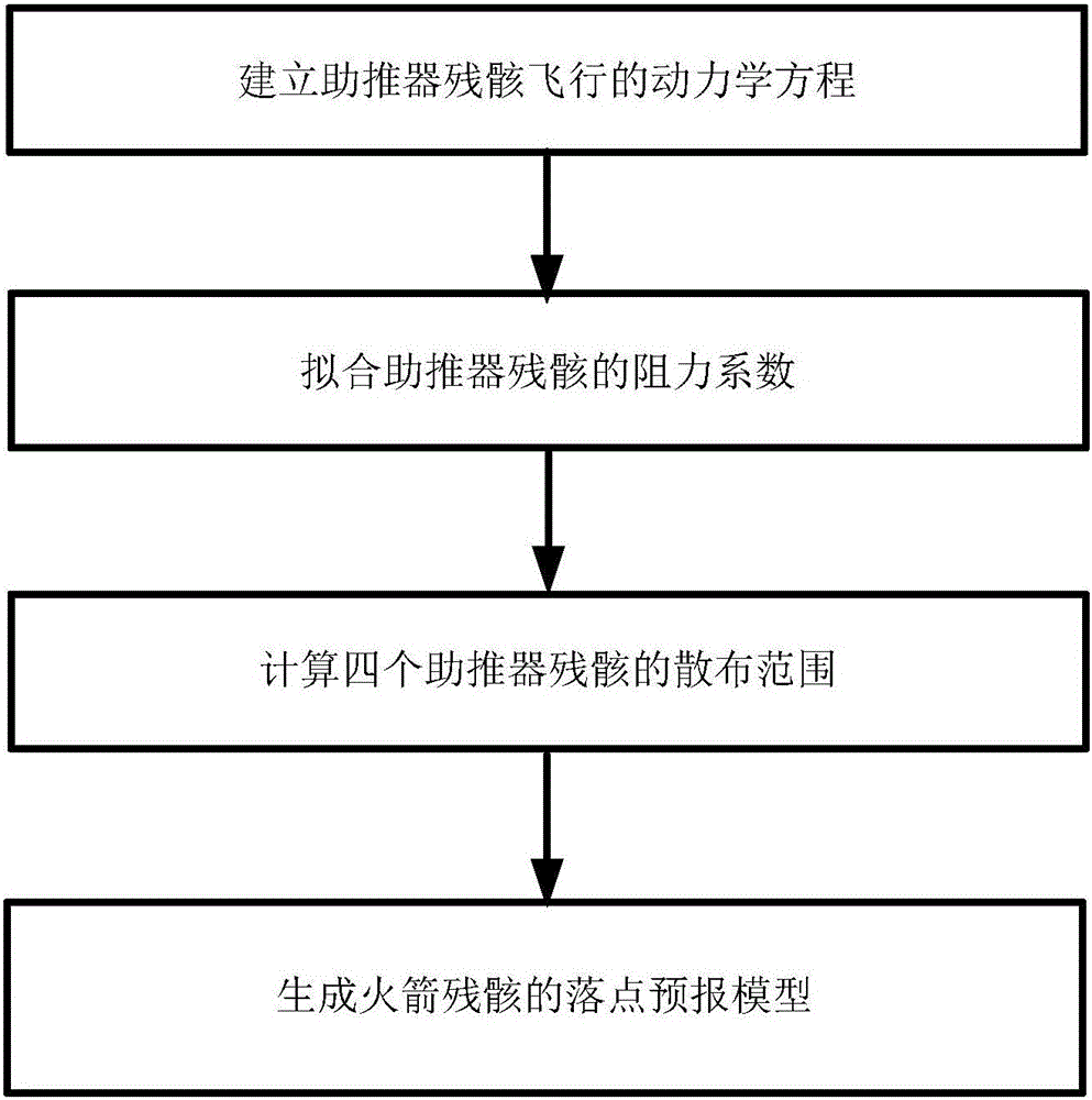
[0040] Such as figure 1 Shown, a kind of generation method of the impact prediction model of rocket wreckage, described method comprises:

[0041] Step S1) establishing the dynamic equation of booster wreckage flight;

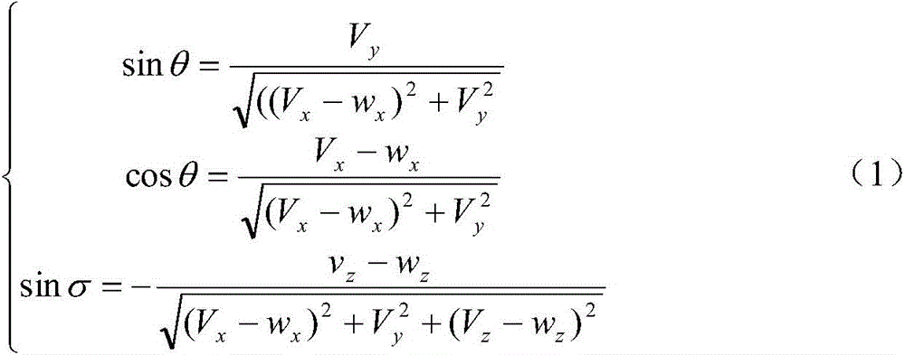
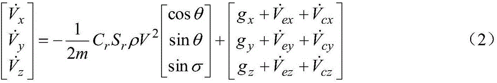
[0042] After the booster wreckage is separated from the arrow-ship complex, it is in an uncontrolled flight state under the action of the earth’s gravity, air resistance, wind force and earth rotation. Let the coordinates of the booster wreckage in the launch system be (x, y, z ), the velocity is (V x ,V y ,V z ), where the projection of the high-altitude wind in the launch coordinate system is: (w x ,0,w z ), then the dynamic equations of the wreckage are:

[0043] sin θ = ...


PUM


Abstract

The invention provides impact point prediction model generation and positioning methods for rocket debris. The impact point prediction model generation method comprises the steps of establishing a dynamic equation of the booster debris flight; fitting a drag coefficient in the dynamic equation using telemetering inertial navigation data of rocket booster debris separation points in all previous missions, upper air data and actual impact point data of the booster debris; then calculating a spreading region of the rocket booster debris according to the calculation impact points of the rocket booster debris in all the previous missions and actual impact points of four boosters; and thus generating a impact point prediction model of the rocket debris. According to the generated impact point prediction model of the rocket debris, the invention further provides a positioning method for the rocket debris. The positioning method is high in theoretical property, simple, and fast and easy to implement, and has significant economic benefits.

Description

technical field [0001] The invention relates to the technical field of rocket wreckage landing area positioning, in particular to a method for generating and locating a rocket wreckage drop point prediction model. Background technique [0002] At present, the search for rocket wreckage is based on the wreckage landing area designated by the rocket technology development unit. Due to the large range of wreckage landing areas, it is more difficult to organize and coordinate work such as traffic control, security, and personnel evacuation. The search work brings a certain degree of blindness; and factors such as complex terrain and inconvenient transportation in the wreckage landing area make the search workload heavy, low in efficiency, and high in cost. [0003] The boosters are the main power source of the rocket, and there are four in total. Among them, the No. 1 booster is aligned with the launch direction, and the No. 2, No. 3 and No. 4 boosters are arranged in counterclo...

Claims


Application Information

Patent Timeline
IPC IPC(8): G06Q10/04
Inventor 王景国杜运新赵华山李鑫沈永康李丽华张颖张锐马小龙杨舒农
Owner 王景国
Why Eureka
Try Eureka