Free Piston Internal Combustion Linear Generator

A linear generator, internal combustion linear technology, applied in free-piston engines, machines/engines, electromechanical devices, etc., can solve problems such as low energy utilization, limited mechanical spring life, large generator mover mass, etc., to improve power density. and power generation capacity, reduce elastic recovery devices, and improve the effect of energy utilization efficiency

Active Publication Date: 2019-03-15
NINGBO INST OF MATERIALS TECH & ENG CHINESE ACADEMY OF SCI
View PDF5 Cites 0 Cited by
  • Summary
  • Abstract
  • Description
  • Claims
  • Application Information

AI Technical Summary

Problems solved by technology

The mechanical spring is limited by its lifespan and cannot be used for a long time
The German DLR Laboratory and the American Sandia Laboratory proposed a mid-mounted dual-piston internal combustion linear generator structure. This structure effectively reduces the vibration of the system through the work of the dual pistons. A two-stage generator is used. The use of electric process assistance reduces the heating caused by the internal combustion engine compression elastic recovery device and improves the utilization rate of system energy, but the practical application is limited because the elastic recovery device is still required
[0004] In the above structure, due to the existence of the elastic recovery device, energy consumption is caused during the energy storage process, the energy utilization rate is low, the mass of the generator mover is large, and the area of ​​the cutting magnetic force line is small, resulting in low energy density, and the free piston internal combustion engine cannot be fully utilized The advantages

Method used


Image

  • Free Piston Internal Combustion Linear Generator
  • Free Piston Internal Combustion Linear Generator
  • Free Piston Internal Combustion Linear Generator

Examples


Embodiment Construction

[0035] In order to make the technical solution of the present invention clearer, the free-piston internal combustion linear generator of the present invention will be further described in detail below in conjunction with the accompanying drawings. It should be understood that the specific embodiments described here are only used to explain the present invention and not to limit the present invention.

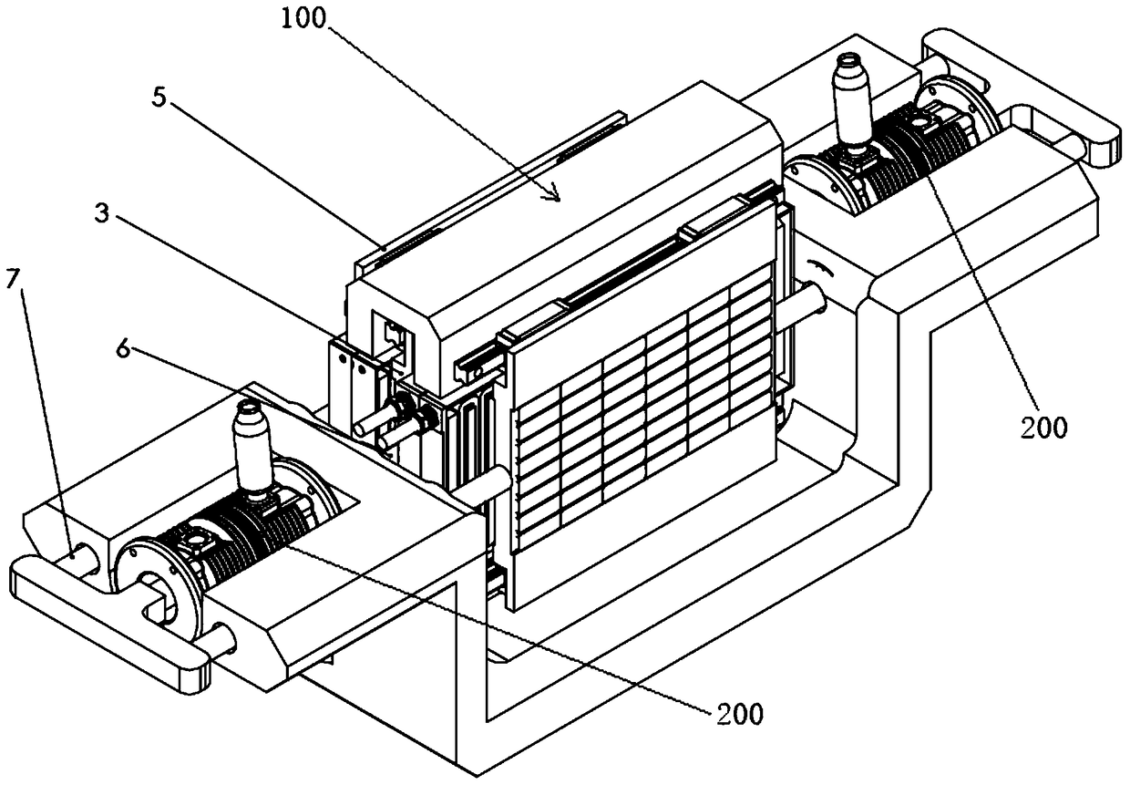
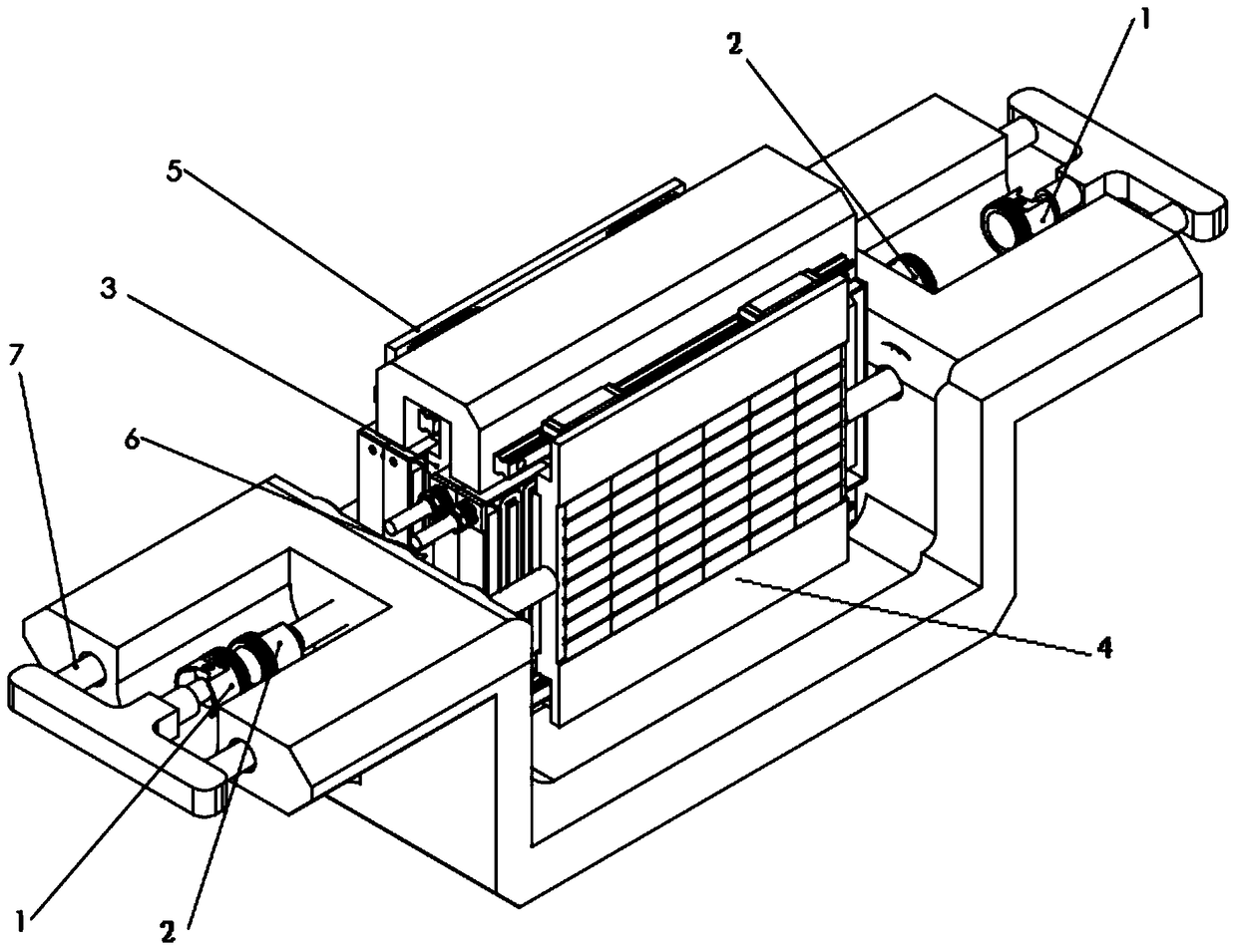
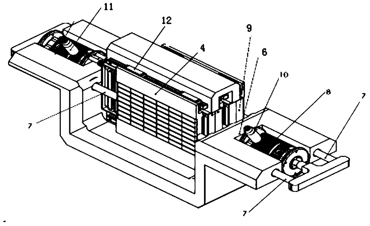
[0036] see Figure 1 to Figure 5 ,Such as figure 1 As shown, the free-piston internal combustion linear generator of the present invention includes a linear generator 100 and two internal combustion engines 200 , and the two internal combustion engines 200 are arranged symmetrically with respect to the linear generator 100 . In this embodiment, the linear generator 100 is preferably a flat linear generator or a cylindrical linear generator. Moreover, according to different operating conditions, the linear generator 100 can also work in the electric state to realize system star...


PUM


Abstract

The invention provides a free piston type internal combustion linear generator. The free piston type internal combustion linear generator comprises a linear generator body and two internal combustion engines. The two internal combustion engines are symmetrically arranged relative to the linear generator body. The linear generator body comprises a stator, an inner rotor and an outer rotor. The two ends of the inner rotor are connected to inner pistons of the two internal combustion engines correspondingly. The two ends of the outer rotor are connected to outer pistons of the two internal combustion engines correspondingly. The two internal combustion engines conduct igniting alternately, so that the inner pistons drive the inner rotor to do reciprocating motion along the stator to cut a magnetic force line of the stator so that power can be generated, the outer pistons drive the outer rotor to do reciprocating motion along the stator to cut the magnetic force line of the stator so that power can be generated, and the motion direction of the outer rotor is opposite to that of the inner rotor. According to the free piston type internal combustion linear generator, the power density and the power generation capacity of the linear generator are improved, so that the energy utilization efficiency is improved.

Description

technical field [0001] The invention relates to the technical field of generators, in particular to a free-piston internal combustion linear generator. Background technique [0002] The free-piston internal combustion linear power generation system is directly coupled with the free-piston internal combustion engine and the linear generator, and the left and right combustion chambers alternately expand and do work to drive the linear generator to reciprocate to generate electricity. The mechanical structure of this device omits the crank linkage mechanism and mechanical flywheel that convert the reciprocating motion of the piston into rotational motion, and directly uses the reciprocating motion of the piston in the combustion chamber to drive the linear motor to generate electricity, and directly converts the heat energy generated by fuel combustion into electrical energy output. The mechanical efficiency is improved, and the compression ratio can be adjusted without changin...

Claims


Application Information

Patent Timeline
Patent Type & Authority Patents(China)
IPC IPC(8): F02B71/04H02K35/02
Inventor 赵飞张杰张驰孙鹏陈进华廖有用杨桂林
Owner NINGBO INST OF MATERIALS TECH & ENG CHINESE ACADEMY OF SCI
Why Eureka
Try Eureka