An automatic feeding device for a rotorless vulcanizer

A technology of automatic feeding and vulcanization instrument, which is applied in the direction of instruments, analytical materials, thin material processing, etc., can solve the problems of complex structure of automatic vulcanizing machine, and achieve the effect of stable transmission, high reliability and precision

Active Publication Date: 2018-01-02
GOTECH TESTING MACHINES DONGGUAN
View PDF8 Cites 0 Cited by
  • Summary
  • Abstract
  • Description
  • Claims
  • Application Information

AI Technical Summary

Problems solved by technology

[0003] The structure of the automatic vulcanizer described in the above patent document is relatively complex. This patent document will disclose an automatic feeding device for a rotorless vulcanizer with a simple structure, high reliability and precision.

Method used


Image

  • An automatic feeding device for a rotorless vulcanizer
  • An automatic feeding device for a rotorless vulcanizer
  • An automatic feeding device for a rotorless vulcanizer

Examples


Embodiment Construction

[0024] In order to further understand the features, technical means, and specific objectives and functions achieved by the present invention, the present invention will be described in further detail below with reference to the accompanying drawings and specific embodiments.

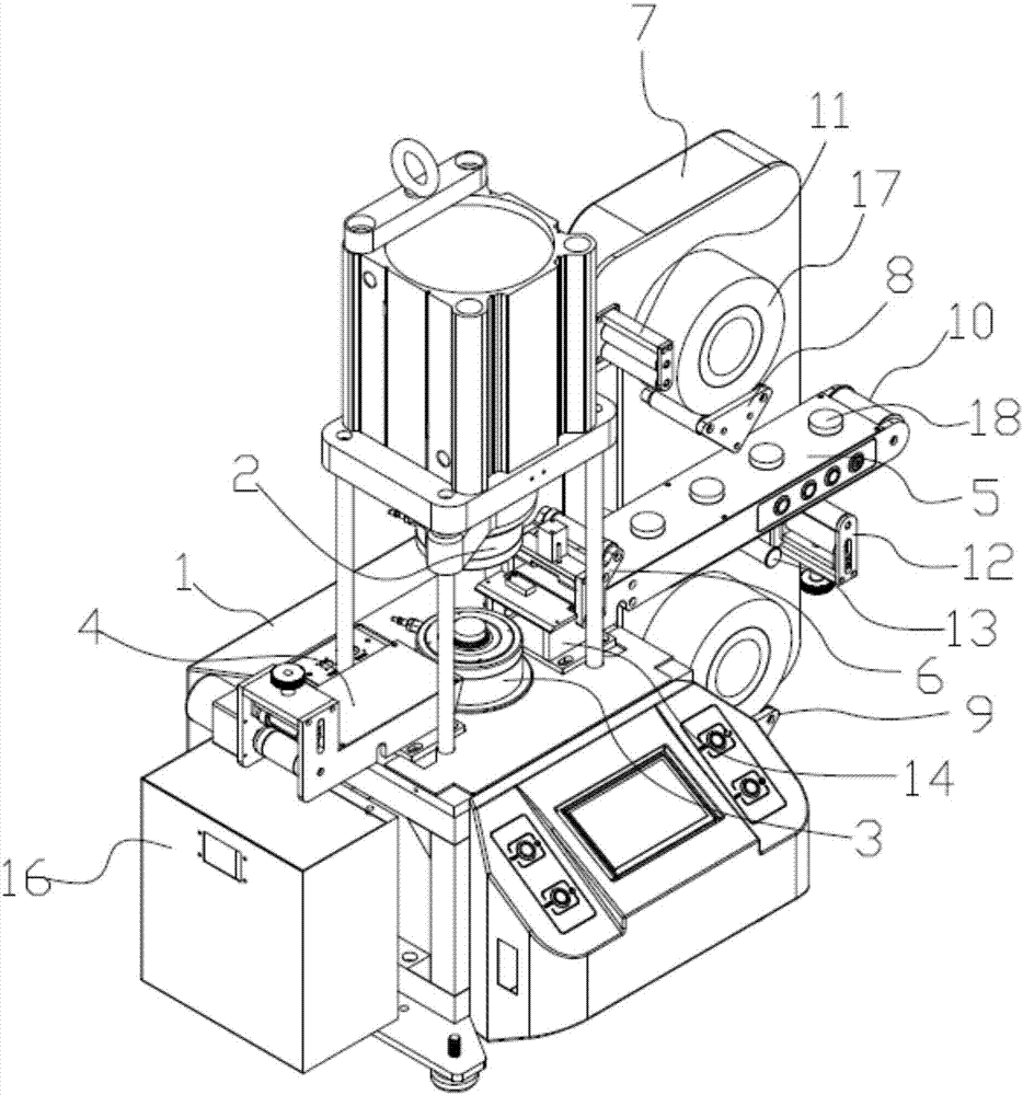
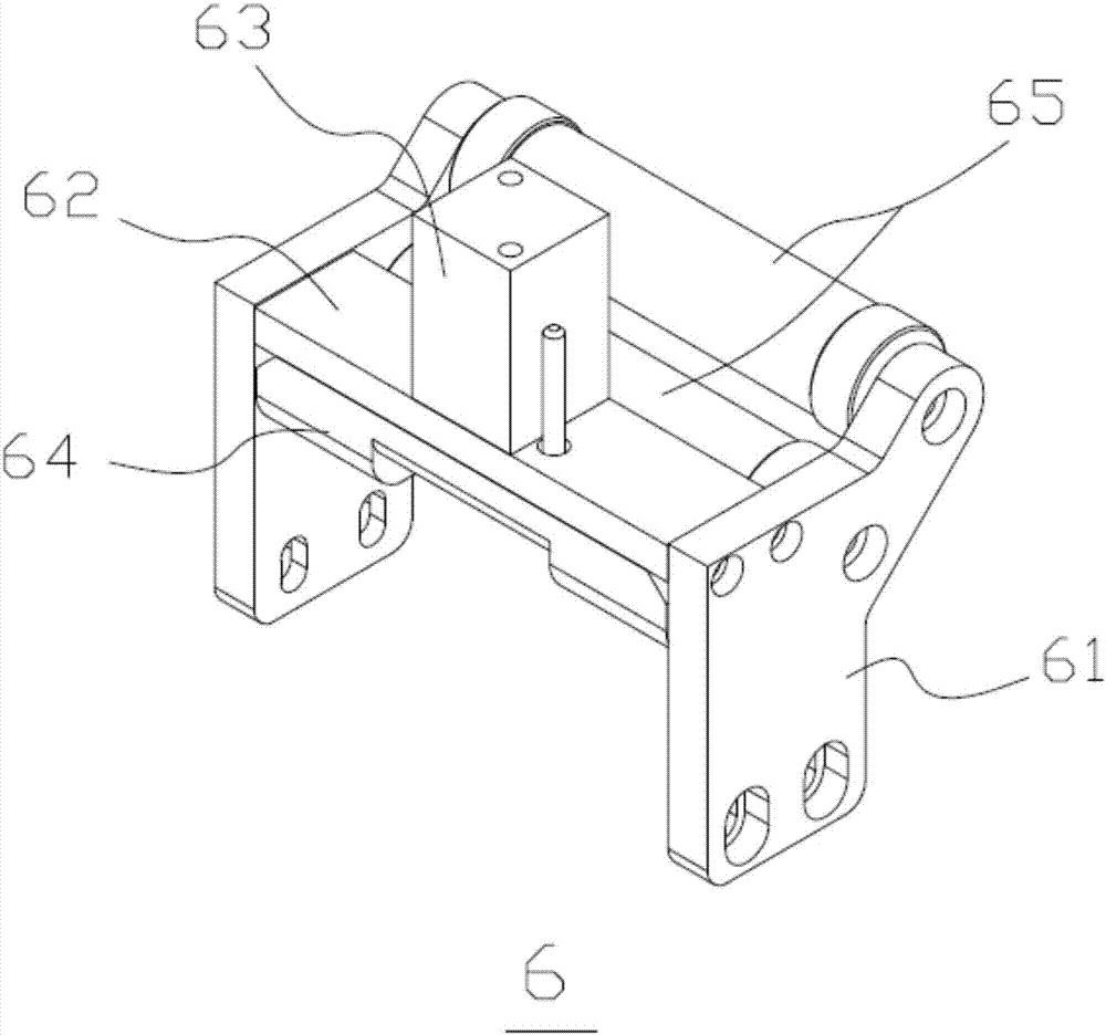
[0025] See figure 1 with Image 6 , The present invention discloses an automatic feeding equipment for a rotorless vulcanizer, which includes an organic table. The machine table 1 is provided with an upper mold 2 and a lower mold 3, and the machine table 1 is located on the left side of the lower mold 3. Waste recycling agency 4.

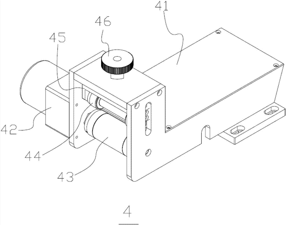
[0026] The waste recycling mechanism 4 includes a bracket seat 41. One end of the bracket seat 41 is connected to the machine table 1, and the other end is provided with a motor 42 on the outside. The motor 42 is axially connected to the lower roller 43 in the bracket seat 41. The bracket seat 41 Inside the lower roller 43, there is an upper roller 44 which is connected to the con...


PUM


Abstract

The invention provides automatic loading equipment of a non-rotor vulkameter, and relates to automatic equipment. The automatic loading equipment of the non-rotor vulkameter comprises a machine table. An upper mould and a lower mould are arranged on the machine table. A waste recovery mechanism is arranged in the position, on the left side of the lower mould, of the machine table. A loading table is arranged in the position, on the right side of the lower mould, of the machine table. A pressing device is arranged at the end, pointing to the machine table, of the loading table. A free idler wheel is arranged at the end, away from the machine table, of the loading table. A mounting plate is arranged on the side of the loading table. An upper bracket is arranged at the upper end of the side, pointing to the loading table, of the mounting plate and located above the loading table. A lower bracket is arranged at the lower end of the side, pointing to the loading table, of the mounting plate, and located below the loading table. The automatic loading equipment of the non-rotor vulkameter is simple in structure, easy to operate and high in accuracy and stability.

Description

Technical field [0001] The invention relates to the field of automation equipment, in particular to an automatic feeding equipment without a rotor vulcanizer. Background technique [0002] At present, when the vulcanizer is tested, it is manually carried out the reclaiming and feeding test of a single sample. During the test, the test time of a single sample is relatively short. In this way, the test actions of the reclaiming and feeding are quite frequent, which is even more uncomfortable. During the test, the rubber smell of some test samples is very pungent. Based on this, the company developed an automatic vulcanizing machine in 2011, such as the Chinese patent number 201110223307.4, which is named the invention patent of the automatic vulcanizing machine. This patent document An automatic vulcanizing machine is described in the article, which includes a frame, a bottom box is arranged under the frame, an upper module and a lower module are arranged in the frame, and a discha...

Claims


Application Information

Patent Timeline
Patent Type & Authority Patents(China)
IPC IPC(8): B65H23/26B65H20/02B65H23/188G01N35/00
CPCB65H20/02B65H23/188B65H23/26B65H2701/11332G01N35/00
Inventor 陈建宏罗迺玮蔡伯轩
Owner GOTECH TESTING MACHINES DONGGUAN
Why Eureka
Try Eureka