Electrical equipment and its control circuits

A technology for controlling circuits and electrical equipment, applied in the field of circuits, can solve the problems of many steps, complicated operation, and high power consumption of electrical equipment

Active Publication Date: 2018-08-10
GREE ELECTRIC APPLIANCES INC
View PDF4 Cites 0 Cited by
  • Summary
  • Abstract
  • Description
  • Claims
  • Application Information

AI Technical Summary

Problems solved by technology

[0004] However, this process of continuously manually performing standby operations has many steps and complicated operations, and it cannot be standby in time when the washing machine is not in use, resulting in high power consumption of electrical equipment.

Method used


Image

  • Electrical equipment and its control circuits
  • Electrical equipment and its control circuits
  • Electrical equipment and its control circuits

Examples


Embodiment 1

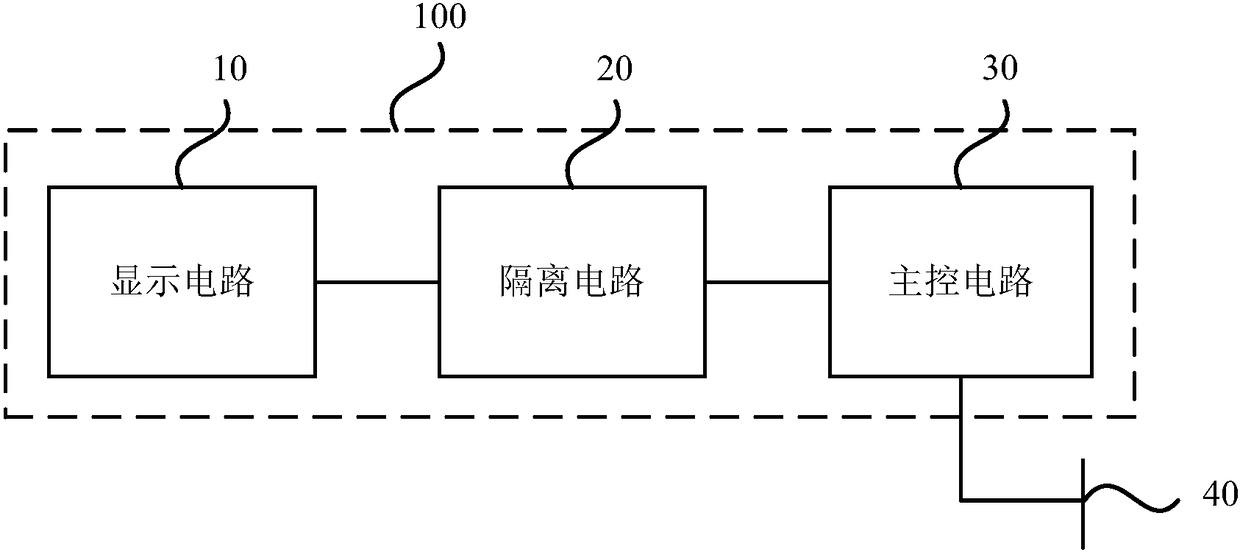
[0018] figure 1 It is a schematic structural diagram of an electrical equipment control circuit provided in Embodiment 1 of the present invention, and the control circuit is used to reduce the power consumption of electrical equipment, such as figure 1 As shown, the control circuit 100 includes: a display circuit 10, an isolation circuit 20 and a main control circuit 30, wherein the display circuit 10 is electrically connected to the input end of the isolation circuit 20, and is used to generate a first start signal according to a start command input by the user , and transmit the first start signal to the isolation circuit 20; the isolation circuit 20 is used to isolate and convert the first start signal to generate a second start signal and transmit it to the main control circuit; The control circuit 30 is electrically connected to the main control weak current power supply 40 and the output end of the isolation circuit 20 respectively, and is used for electrically connectin...

Embodiment 2

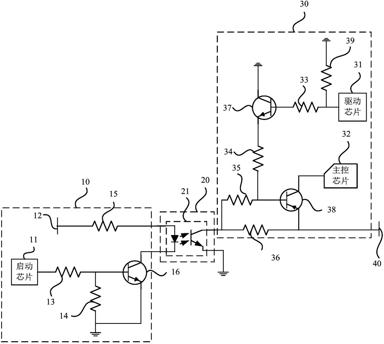
[0027] Figure 2A It is a specific circuit diagram of an electrical equipment control circuit provided by Embodiment 2 of the present invention, and the specific circuit diagram embodies the display circuit 10, the isolation circuit 20 and the main control circuit 30 respectively. Such as Figure 2A As shown, the control circuit is specifically:

[0028] After the electrical equipment is powered on, the main control weak current power supply 40 and the display weak current power supply in the display circuit 10 are powered on.

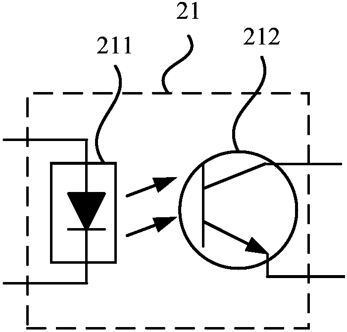
[0029] The isolation circuit 20 includes a photocoupler 21, such as Figure 2B As shown, the photocoupler 21 includes a light emitting source 211 and a receiving light source 212 . Wherein, the light emitting source 211 of the photocoupler 21 is preferably a light emitting diode, and the light receiving source 212 of the photocoupler 21 is preferably an NPN phototransistor, and the emitter of the phototransistor is grounded. Since the power supply ...

Embodiment 3

[0045] An embodiment of the present invention provides an electrical device. In order to reduce consumption and save energy of the electrical device, the control circuit 100 of the electrical device provided by the embodiment of the present invention is configured in the electrical device.

[0046] Exemplarily, the electrical equipment may be a washing machine, and the washing machine may further include a display panel; the display panel has a power-on switch, a power-off switch, a standby start switch, and a standby switch.


PUM


Abstract

The embodiment of the invention discloses electrical equipment and a control circuit thereof.The control circuit comprises a display circuit, a main control circuit and an isolation circuit; the display circuit is electrically connected to the input endof the isolation circuit; a main control weak power source and the output end of the isolation circuit are electrically connected to the main control circuit respectively. In the electrical equipment and the control circuit thereof, the display circuit generates a first start signal based on a start command from a user, the first start signal is converted into a second start signal through the isolation circuit and is sent to the main control circuit, so that the main control circuit is electrically connected to the main control weak power source, the electric connection between the main control circuit and the main control weak power source is disconnected when the main control circuit receives a command about turn-off or does not receive any operation command within the set time, accordingly the awakening and self-turn-off of the circuit power source are achieved, and the power consumption of the circuit is reduced.

Description

technical field [0001] The embodiments of the present invention relate to the technical field of circuits, and in particular to an electrical device and a control circuit thereof. Background technique [0002] For commonly used household appliances, such as washing machines, in order to save electric energy, users usually unplug the plug to disconnect the power supply when not in use, and then plug in the plug to turn on the power supply when in use. Although it can reduce electrical power consumption and save electric energy, but In the long run, it will have a certain impact on the components of electrical appliances. [0003] In the prior art, in order to solve the above problems, a standby circuit is configured in the electric appliance. For example, generally after the power is plugged in, the washing machine starts to be in a standby state. Just need manual operation to start power supply when using washing machine, now washing machine starts to work; [0004] Howev...

Claims


Application Information

Patent Timeline
Patent Type & Authority Patents(China)
IPC IPC(8): G05F1/625
CPCG05F1/625
Inventor 陶坤元许敏郭清风
Owner GREE ELECTRIC APPLIANCES INC
Why Eureka
Try Eureka