
Hydraulic loom splash-proof type nozzle
A water-jet loom and anti-splash technology, applied in looms, textiles, textiles, and papermaking, can solve problems such as poor speed, unfavorable environmental protection, and affecting weft insertion operations, so as to reduce the formation of spray and improve the use of The effect of improving lifespan and agglomeration
- Summary
- Abstract
- Description
- Claims
- Application Information
AI Technical Summary
Problems solved by technology
Method used
Image

Examples
Embodiment 1
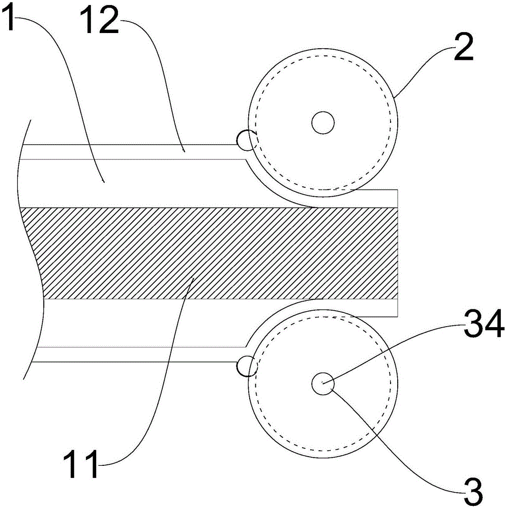
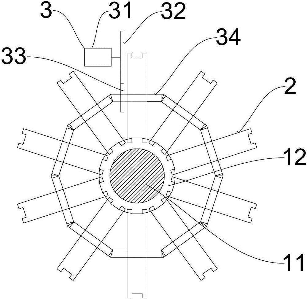
[0022] Such as figure 1 with figure 2 As shown, the present invention provides a splash-proof spout for a water jet loom, comprising: a sprinkler head 1, in which a main water channel 11 and a secondary water channel 12 are provided, and the secondary water channel 12 is arranged in the main water channel 11 The main water channel 11 and the secondary water channel 12 are independent of each other, and the water outlet of the main water channel 11 and the water outlet of the secondary water channel 12 are on the same plane; multiple water guide wheels 2, multiple The water guide wheel 2 is arranged around the nozzle 1 and the wheel side of each water guide wheel 2 extends into the auxiliary water channel 12; the driving mechanism 3, the driving mechanism 3 and the plurality of water guides The wheel 2 is connected in transmission to drive a plurality of the water guide wheels 2 to rotate synchronously. Through the design of the above structure, the water flow in the secondary ...
Embodiment 2
[0024] As a specific implementation of the first embodiment, the drive mechanism 3 includes: a motor 31, a main gear 32, a secondary gear 33, and a plurality of drive shafts 34, the drive shaft 34 and the water guide wheel 2 one by one Correspondingly, and each drive shaft 34 is arranged in the middle of the water guide wheel 2 corresponding to it to drive the rotation of the water guide wheel 2, and the output end of the motor 31 is fixedly connected to the main gear 32, so The main gear 32 meshes with the auxiliary gear 33, the auxiliary gear 33 is sleeved on one of the drive shafts 34 and is integrally formed with the drive shaft 34, and the motor 31 passes through the main gear 32 The driving shaft 34 integrally formed with the auxiliary gear 33 is driven to rotate with the auxiliary gear 33, a plurality of the driving shafts 34 are connected end to end, and each two adjacent driving shafts 34 pass through a cone. Gear transmission connection, through the design of the abov...
Embodiment 3
[0026] As a specific implementation of the above embodiment 1, the outer circumferential surface of each water guide wheel 2 is recessed inward to form an annular groove, and the outer wall of the secondary water channel 12 protrudes outward in the secondary water channel 12 An annular recess is formed in the annular recess, and a plurality of water stop balls corresponding to the water guide wheel 2 are arranged in the ring recess, each of the water stop balls and the corresponding annular groove of the water guide wheel 2 The bottom of the groove is opposed to each other, and the auxiliary water channel 12 is provided with an opening for each of the water guide wheels 2 to extend. Because in order to facilitate the rotation of each water guide wheel 2, each water guide wheel 2 extends After entering the secondary water channel 12, the corresponding opening on the secondary water channel 12 needs to have a certain gap. For this reason, an annular groove can be provided on each ...
PUM
 Abstract
Description
Claims
Application Information