Durability testing device for test piece under load and environment coupling effect

A technology of durability test and test device, which is applied in the direction of measuring device, strength characteristics, instruments, etc., to achieve the effect of ensuring accuracy

Inactive Publication Date: 2017-05-31
HUBEI UNIV OF TECH
View PDF9 Cites 5 Cited by
  • Summary
  • Abstract
  • Description
  • Claims
  • Application Information

AI Technical Summary

Problems solved by technology

It mainly solves the independent effect of force loading and erosion environment

Method used


Image

  • Durability testing device for test piece under load and environment coupling effect
  • Durability testing device for test piece under load and environment coupling effect
  • Durability testing device for test piece under load and environment coupling effect

Examples


example 1

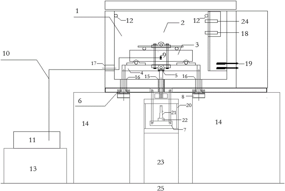
[0041] Example 1: Bending loading test on specimen under multi-factor environment

[0042] The durability test device for loading and testing the bending test members is as follows: figure 1 shown. The specific implementation steps are:

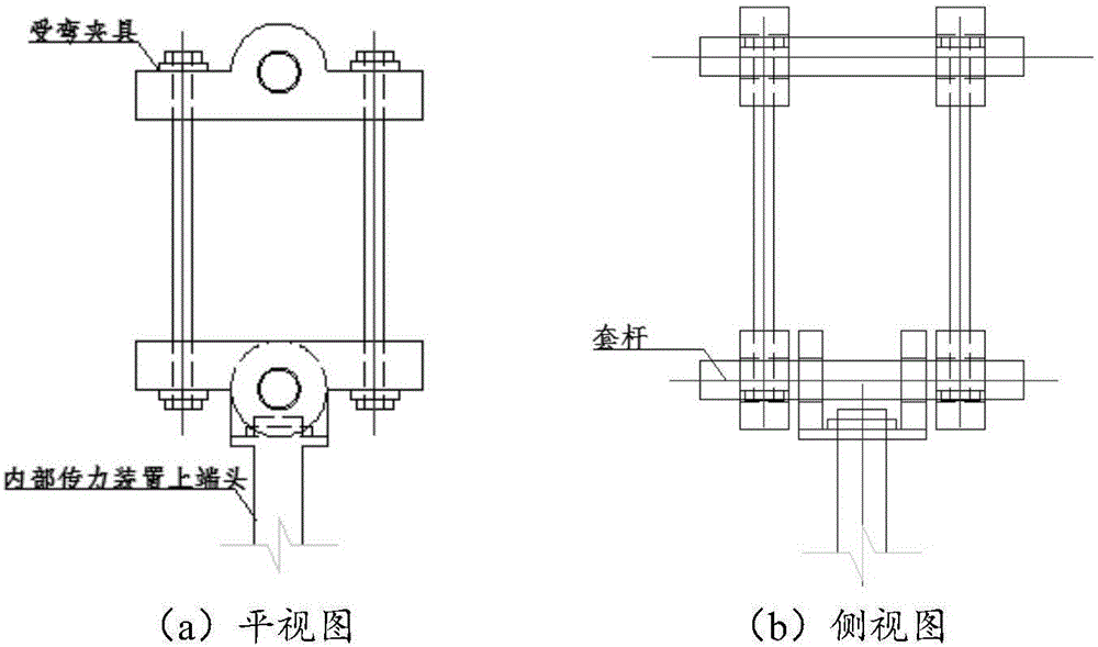
[0043] (1) Set the bending test piece 3 with 2 bending loading fixtures. For details of the bending loading fixtures, see image 3 . The data measurement and recording device 1 is arranged on the test piece 3 , and the corresponding test leads 10 protrude through the holes 17 and are connected with the data measurement and recording system 11 . Open the working cabin 1 of the test device, place the bending test piece 3 and the loading fixture 2 in the designated position in the working cabin 1; (2) connect the loading fixture 2 and the upper end of the internal force transmission device 5 through a sleeve rod (see Figure 5 ), close the working cabin 1; (3) open the jack 21, adjust the lifting force of the jack 21 according to the sensor ...

example 2

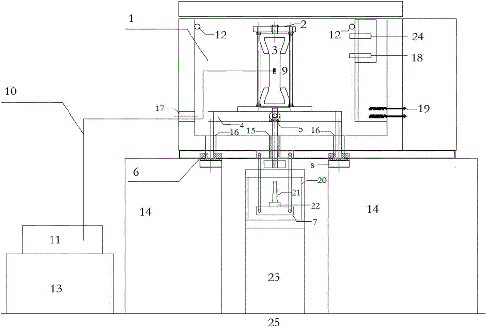
[0044] Example 2: Axial tensile loading test on test member under multi-factor environment

[0045] The durability test device for loading and testing the axial tension test members is as follows: figure 2 shown. The specific implementation steps are:

[0046] (1) Set the axial tension test piece 3 with two axial tension loading fixtures. For details of the axial tension loading fixture, see Figure 4 . The data measurement and recording device 1 is arranged on the test piece 3 , and the corresponding test leads 10 protrude through the holes 17 and are connected with the data measurement and recording system 11 . Open the working cabin 1 of the test device, place the bending test piece 3 and the loading fixture 2 in the designated position in the working cabin 1; (2) connect the loading fixture 2 and the upper end of the internal force transmission device 5 through a sleeve rod (see Figure 5 ), close the working cabin 1; (3) open the jack 21, adjust the lifting force of ...


PUM


Abstract

The invention discloses a durability testing device for a test piece under a load and environment coupling effect. The durability testing device comprises a working cabin, a loading jig, a test piece, an internal force transmitting device, an external force transmitting device, an internal support, an external support, a jack, a reaction frame and a testing system, wherein the external support is fixed on the ground; the working cabin is mounted on the external support; the internal force transmitting device, the loading jig and the test piece are mounted on the internal support in the working cabin, penetrate through holes through the internal force transmitting device, and are connected with the external force transmitting device; the external force transmitting device is connected with the jack and the reaction frame; the jack transmits jacking force to the external force transmitting device through opening of the jack, and further the force is transmitted to the internal force transmitting device and the loading jack, and is finally transmitted to the test piece, so that the fact that load is applied to the test piece in the working cabin is realized. The testing device has the advantages that application of load is not affected when the environment is changed, and an environmental effect is not affected when load is applied, so that variation of the environment and variation of the load are mutually independent and the environment and the load are interacted.

Description

technical field [0001] The invention belongs to a durability test device for structural materials, in particular to a device for testing the mechanical properties of test pieces under the long-term coupling action of load and environment. Background technique [0002] With the development of the construction industry, the use of concrete structures also involves all aspects of human life. In recent years, accidents caused by insufficient durability of concrete structures have continued to increase, and the issue of concrete durability has attracted more and more attention. In some major projects, such as dams, bridges, ports, etc., and some high-rise buildings, these structures were destroyed before reaching the design period, causing huge economic losses and casualties. [0003] Although there are decades of research on the durability of concrete structures, and there are many related research results, many studies mainly consider environmental factors while ignoring other ...

Claims


Application Information

Patent Timeline
Patent Type & Authority Applications(China)
IPC IPC(8): G01N3/02
CPCG01N3/02G01N2203/0048G01N2203/024
Inventor 李扬徐惟雄汪秋红戴欣
Owner HUBEI UNIV OF TECH
Why Eureka
Try Eureka