Electric demonstrating device for gradual luminescence display

A light-emitting display, progressive technology, applied in the direction of instruments, teaching models, educational appliances, etc., can solve the problems of insufficient types of experimental instruments, inability to popularize teaching instruments, incomplete experimental instruments, etc., to improve quality education, expand imagination space, Operating the effect of a touch

Inactive Publication Date: 2017-06-13
CHONGQING ZUNLAI TECH
View PDF6 Cites 0 Cited by
  • Summary
  • Abstract
  • Description
  • Claims
  • Application Information

AI Technical Summary

Problems solved by technology

Therefore, the various experimental instruments in teaching are constantly improving, but there are still many shortcomings: First, the types of experimental instruments are insufficient, especially the experimental instruments for low-grade students are not comprehensive
Second, the spirit of entertaining and teaching in teaching instruments is not enough. Third, the cost of most teaching instruments is too high. Therefore, for some remote village schools, many common teaching instruments cannot be popularized.
[0005] However, there are difficulties in designing a circuit with a demonstration instrument and at the same time it can become a self-made test circuit for beginners. First, from the demonstration effect, because there are many concepts in electricity, it is a demonstration of that aspect; The design of the instrument is mainly to demonstrate the physical properties of components that are closely related to frequency, such as capacitors and inductances. Only by demonstrating those aspects can their physical properties be fully displayed. Thirdly, the most important point is, Although some circuits can achieve the purpose of demonstration, they cannot be an excellent self-made experimental circuit, because an excellent self-made experimental circuit also involves the subject of each unit experiment, which is suitable for beginners, and at the same time it also involves the interest of beginners, and Whether it is easy to install successfully and so on, so this kind of excellent line must also be enriched, innovated and developed

Method used


Image

  • Electric demonstrating device for gradual luminescence display
  • Electric demonstrating device for gradual luminescence display

Examples


Embodiment Construction

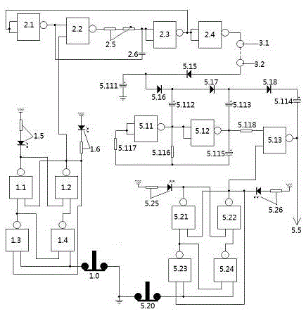
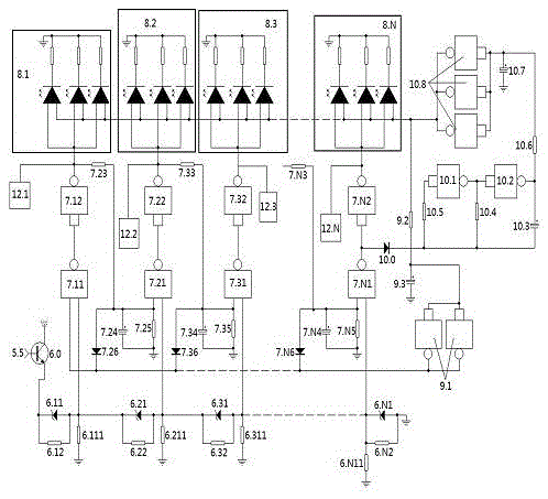
[0145] figure 1 , figure 2 It is a way of concrete implementation.

[0146] 1. Select components: power amplifier one is composed of three two-input NOT gates connected in parallel, and power amplifier two is composed of two two-input NOT gates connected in parallel. The pulse resistance is composed of an adjustable resistance and a fixed resistance in series. The preamp tube is an NPN transistor.

[0147] 2. Welding: an electrical demonstrator with progressive luminous display, except for the display system, the electronic circuits of each part are as follows: figure 1 welded as shown, the display system presses figure 2 Welded as shown.

[0148] Three, debugging.

[0149] 1. Check and debug the ring pulse unit.

[0150] Disconnect the normally closed contact of the switching button of the four-door electronic switch, that is, the switching button is not connected to the ground wire, and the output of the four-door electronic switch is high, and the output of the thr...


PUM


Abstract

The invention relates to an electric demonstrating device for gradual luminescence display, belonging to the teaching apparatus demonstration field. The electric demonstrating device consists of a test hole, an oscillatory type amplification unit, a loop pulse unit, a four-door type electronic switch, a display pre-unit, a display system and a voice grade. The test hole is connected with a tested element, after going through the element, the voltage of the loop pulse unit can be lowered to some extent, after amplified and adjusted by the oscillatory type amplification unit, the display pre-unit can be reliably started to excite the display system and the voice grade to form prompt of sound and light, and the display system is provided with a display driver stage, a display level, a power amplifier stage and a display oscillator stage to form a common cathode luminescent tube in the display stage, which is capable of giving out different rays of light. The electric demonstrating device has certain interestingness, can be used for training a large number of teenagers to love science, and plays an active part in improving the basic quality of students.

Description

technical field [0001] The utility model belongs to the field of teaching instrument demonstration. Background technique [0002] Innovation is the soul of a nation, and young students are the power of innovation. [0003] The strength of a country lies in its talents, and the cultivation of talents lies in education. The focus of education on young people is that the country is strong when young people are strong, and the country progresses when young people progress. To cultivate young people's love for science, improving the quality of teaching is the key, and the accuracy of experimental instruments is an important factor in improving teaching. The experiments are more convincing, so that students can understand things, understand natural phenomena, inspire students' thinking, and play an important role in improving the level of education. Therefore, various experimental instruments in teaching are constantly improving, but there are still many deficiencies: First, the...

Claims


Application Information

Patent Timeline
Patent Type & Authority Applications(China)
IPC IPC(8): G09B23/18
CPCG09B23/183
Inventor 蒋丹杨远敏
Owner CHONGQING ZUNLAI TECH
Why Eureka
Try Eureka