Steam valve with rotary bubble breaker

A steam valve and foam-breaking technology, which is applied in the field of kitchen appliances, can solve problems such as unsatisfactory foam-breaking effect, low foam-breaking efficiency, and unstable operation, and achieve good anti-overflow effect, stable foam-breaking effect, and good foam-breaking effect Effect

Active Publication Date: 2017-08-15
HONGYANG HOME APPLIANCES
View PDF6 Cites 8 Cited by
  • Summary
  • Abstract
  • Description
  • Claims
  • Application Information

AI Technical Summary

Problems solved by technology

However, the foam-breaking efficiency of a single rotating foam-breaker is low, and the foam-breaking effect is not ideal. When the steam volume is large, it is easy to run unstable due to the excessive impact of the steam received, too concentrated, and it is easy to be damaged by the adhesion of rice foam and the like. Slow down or even stop under strong liquid adhesion

Method used


Image

  • Steam valve with rotary bubble breaker
  • Steam valve with rotary bubble breaker
  • Steam valve with rotary bubble breaker

Examples


Embodiment 1

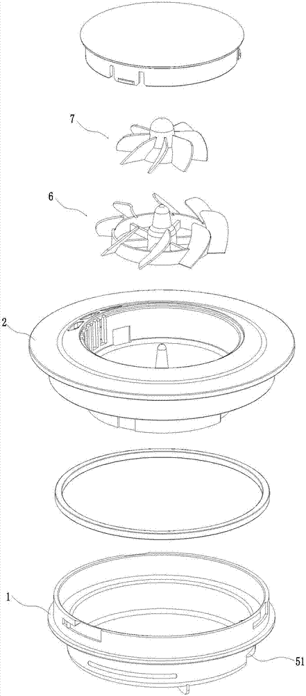
[0036] Such as figure 1 As shown, the first rotating bubble breaking member 6 and the second rotating foam breaking member 7 are nested, and the central axes of the two are coincident. The first rotating foam breaking member 6 and the second rotating foam breaking member 7 are nested, occupying a small space and not affecting the compactness of the steam valve structure. After nesting, the central axis of the two coincides, the airflow interference received during rotation is small, and the foam breaking effect is better.

[0037] The nesting can be partial nesting or full nesting, that is, the second rotating bubble breaking member 7 is at least partially located in the accommodation cavity formed by the first rotating bubble breaking member 6 .

[0038] Such as figure 1 The shown first rotating foam breaking member 6 and the second rotating foam breaking member 7 are horizontally nested, that is, the first rotating foam breaking member 6 and the second rotating foam breaki...

Embodiment 2

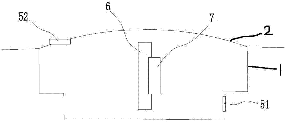
[0042] Such as image 3 As shown, in this embodiment, the first rotating foam breaking member 6 and the second rotating foam breaking member 7 are both arranged horizontally, and both the first rotating foam breaking member 6 and the second rotating foam breaking member 7 can be positioned at The steam ejected from the steam inlet 51 is driven to rotate horizontally. The second rotating bubble breaking member 7 is located above the first rotating bubble breaking member 6, and the central axes of the two are coincident. The two rotating bubble breakers are installed independently. The first rotating bubble breaker 6 may be installed on the valve seat 1 (not shown in the figure), and the second rotated bubble breaker 7 may be installed on the valve cover 2 (not shown in the figure). shown), reduces the requirements on the machining accuracy of the two rotating bubble breaking parts, even if there is a machining accuracy error, it will not affect the assembly, and the wind gene...

Embodiment 3

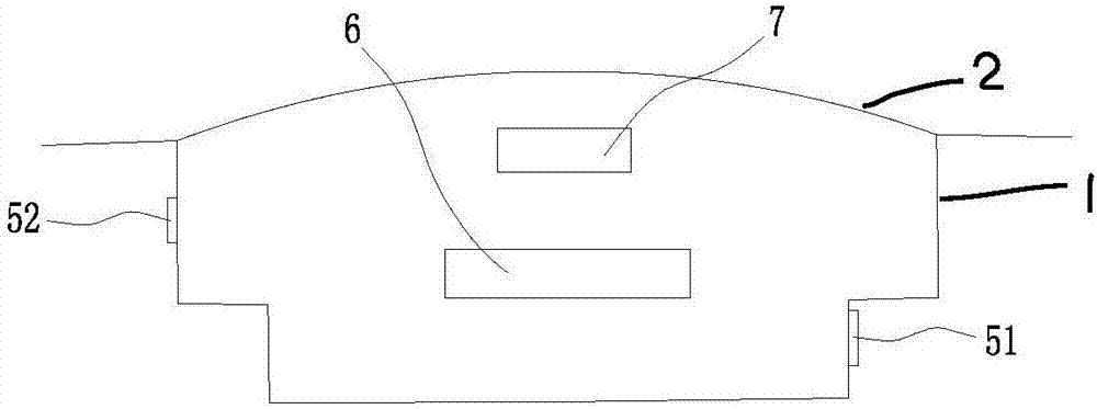
[0045] Such as Figure 4 As shown, in this embodiment, the first rotating foam breaking member 6 and the second rotating foam breaking member 7 are both arranged horizontally, and both the first rotating foam breaking member 6 and the second rotating foam breaking member 7 can be positioned at The steam ejected from the steam inlet 51 is driven to rotate horizontally. The two rotating bubble breakers are arranged horizontally side by side. The two rotating bubble breakers are installed independently. The first rotating foam breaking member 6 can be installed on the valve seat 1 or on the valve cover 2 (not shown in the figure), and the second rotating foam breaking member 7 can also be installed Installed on the valve seat 1 or on the valve cover 2 (not shown in the figure), the requirements for machining accuracy of the two rotating bubble breaking parts are reduced, even if there is an error in machining accuracy, the assembly will not be affected. Moreover, when the two ...


PUM


Abstract

The invention discloses a steam valve with rotary bubble breakers, and aims to solve the problems that an existing steam valve rotary bubble breaker is low in bubble breaking rate, poor in bubble breaking effect, and imbalance in motions; the steam valve comprises a valve seat and a valve cover; the valve seat is provided with a steam inlet; the valve cover and the valve seat can form a steam chamber connected with the steam inlet; the steam valve comprises a first rotary bubble breaker and a second rotary bubble breaker respectively arranged in the steam chamber in a rotary manner, and the rotary bubble breakers can be driven by the steam ejected from the steam inlet to rotate, thus breaking bubbles; the advantages are that the two rotary bubble breakers can be simultaneously driven to rotate, thus providing high bubble breaking rate, dispersing the steam impact force, and ensuring the rotary bubble breakers to stably and normally work; when one rotary bubble breaker fails, the bubble breaking work can be ensured to be normally done, thus preventing the steam valve bubble breaking system failure, and allowing the steam valve to have more stable bubble breaking effect.

Description

technical field [0001] The invention relates to the field of kitchen appliances, in particular to a steam valve with a rotating bubble breaking member. Background technique [0002] The steam valve is an important accessory of the rice cooker, which plays the role of exhausting and breaking bubbles during the use of the rice cooker. The steam valve includes a valve seat and a valve cover arranged on the valve seat. A steam inlet is opened on the valve seat. The valve cover and the valve seat form a steam chamber connected with the steam inlet. , the steam chamber and the steam outlet form a steam channel. In the current steam valve, there is a rotating foam breaker in the steam chamber. The rice bubbles in the rice cooker flow into the steam valve with the steam. . However, the foam-breaking efficiency of a single rotating foam-breaker is low, and the foam-breaking effect is not ideal. When the steam volume is large, it is easy to run unstable due to the excessive impact ...

Claims


Application Information

Patent Timeline
Patent Type & Authority Applications(China)
IPC IPC(8): A47J27/58A47J36/38
CPCA47J27/58A47J36/38
Inventor 朱泽春王翔张国滨
Owner HONGYANG HOME APPLIANCES
Why Eureka
Try Eureka