Pipeline distribution structure of hydrolysis acidification pool

A technology for hydrolyzing and acidizing pools and arranging structures is applied in the field of pipeline layout structures of hydrolyzing and acidifying pools, and can solve the problems of increasing construction difficulty and engineering cost, increasing waterproof casings, and many pipelines.

Inactive Publication Date: 2017-11-17
CHANGYI HAIYANG WATER IND
View PDF0 Cites 0 Cited by
  • Summary
  • Abstract
  • Description
  • Claims
  • Application Information

AI Technical Summary

Problems solved by technology

[0003] 1. Relevant valve wells need to be configured outside the pool, and corresponding valves and expansion joints are installed in the valve wells, such as image 3 , Figure 4 and Figure 5 As shown, the hydrolytic acidification tank 1 is separated to form a plurality of connected hydrolytic acidification sub-pools, and a set of emptying pipelines 11 and a set of overflow pipelines 12 are respectively arranged on each hydrolytic acidification sub-pool, and each set of pipelines must be configured Corresponding valve wells 13, such a hydrolysis and acidification tank 1 sometimes have as many as ten or twenty valve wells correspondingly. The valve wells 13 occupy a large area and are not easy to arrange outside the hydrolysis and acidification tank. In addition, each valve well They are equipped with valves and expansion joints correspondingly, so the project cost is high, and the depth of these valve wells is relatively large, which is not conducive to construction and subsequent maintenance
[0004] 2. Multiple sets of pipelines lead to many pipeline penetration points, all of which need to be waterproofed, which increases the complexity of the project
[0005] 3. The valve well outside the pool is located on the backfill soil, and the foundation sinks unevenly, which may easily cause well cracks and pipe leakage
[0006] 4. In order to do a good job of waterproofing, structures such as waterproof casings will be added, which will increase the difficulty of construction
[0007] 5. There are many pipelines, resulting in waste of pipeline materials, and also increasing the difficulty of construction and project cost

Method used


Image

  • Pipeline distribution structure of hydrolysis acidification pool
  • Pipeline distribution structure of hydrolysis acidification pool
  • Pipeline distribution structure of hydrolysis acidification pool

Examples


Embodiment Construction

[0020] Below in conjunction with accompanying drawing and embodiment, further elaborate the present invention. In the following detailed description, certain exemplary embodiments of the invention are described by way of illustration only. Needless to say, those skilled in the art would realize that the described embodiments can be modified in various different ways, all without departing from the spirit and scope of the present invention. Accordingly, the drawings and description are illustrative in nature and not intended to limit the scope of the claims.

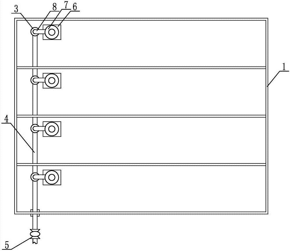
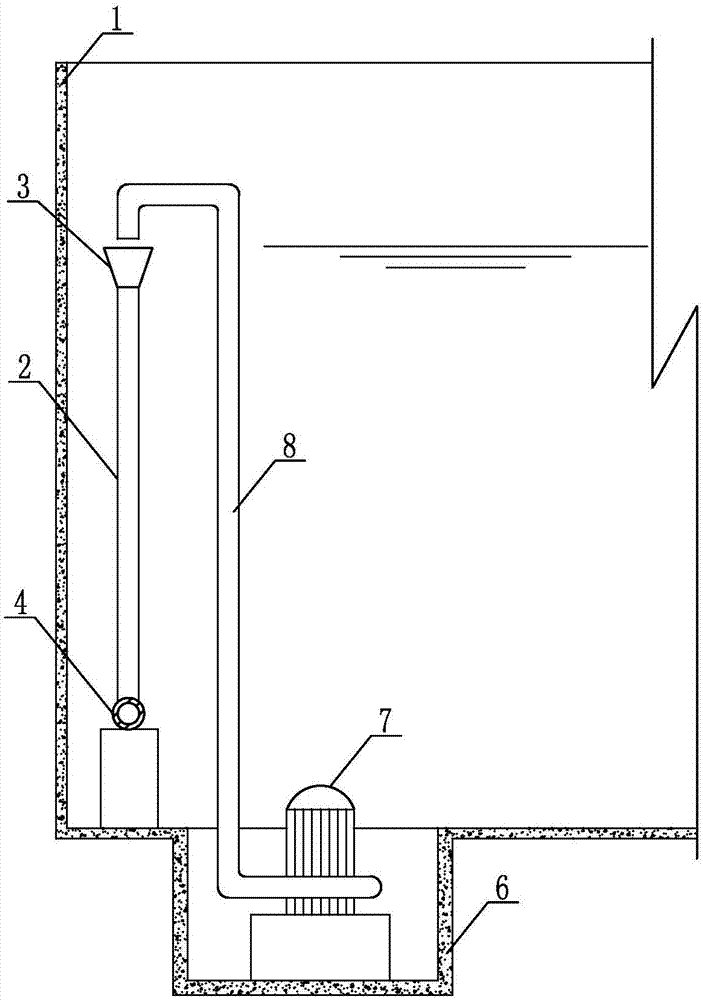
[0021] Such as figure 1 and figure 2 As shown, the pipeline layout structure of the hydrolysis acidification tank is installed in the hydrolysis acidification tank 1, including a number of overflow risers 2 arranged in the hydrolysis acidification tank 1, and the upper ends of the overflow riser 2 are correspondingly installed with overflow ports 3, each The bottom ends of the overflow riser 2 are respectively connec...


PUM


Abstract

The invention discloses a pipeline arrangement structure of a hydrolysis acidification tank, which comprises a plurality of overflow risers arranged in the hydrolysis acidification tank, overflow outlets are installed on the upper ends of the overflow risers, and the bottom ends of each overflow riser are respectively connected to overflow horizontal pipes, and the overflow The horizontal pipe extends to the outside of the hydrolysis and acidification tank, and expansion joints are installed on the overflow horizontal pipe located outside the hydrolysis and acidification tank, and at least one side of the overflow riser is equipped with an emptying device; the overflow system only includes several overflow risers and One overflow horizontal pipe, when emptying, just pull the water outlet end of the emptying device into the overflow port, and it will be discharged from the overflow vertical pipe and overflow horizontal pipe, so the overflow vertical pipe and overflow horizontal pipe are also used as part of the emptying pipeline. The use of pipelines and related control valves and expansion joints is reduced, and valve wells outside the pool are omitted. In addition, the layout of pipelines outside the pool can be reduced, and the sealing points between the pipeline and the hydrolysis acidification tank are reduced, which simplifies the project and reduces engineering difficulty.

Description

technical field [0001] The invention relates to the technical field of sewage treatment, in particular to a pipeline arrangement structure of a hydrolysis acidification tank. Background technique [0002] In the process of sewage treatment, hydrolytic acidification is one of the indispensable treatment processes. Hydrolytic acidification needs to set up a special hydrolytic acidification tank, and the tank body is equipped with emptying pipelines and overflow pipelines. The emptying pipeline and overflow pipeline used in the traditional hydrolytic acidification tank are two sets of independent pipelines, and are equipped with corresponding control valves, expansion joints and other supporting facilities. Most of the supporting facilities and pipeline structures are arranged in Outside the pool, the pipeline layout of the prior art has the following disadvantages: [0003] 1. Relevant valve wells need to be configured outside the pool, and corresponding valves and expansion ...

Claims


Application Information

Patent Timeline
Patent Type & Authority Applications(China)
IPC IPC(8): C02F3/28
CPCC02F3/2866C02F2203/006
Inventor 于富友徐旭涛徐伟康
Owner CHANGYI HAIYANG WATER IND
Why Eureka
Try Eureka