Mixer

A mixer and reducer technology, applied in the field of chemical machinery, can solve the problems of material drop, uneven mixing, and the helical piece cannot fully contact the material, etc.

Inactive Publication Date: 2017-11-24
天津日禾餐饮管理服务有限公司
View PDF1 Cites 2 Cited by
  • Summary
  • Abstract
  • Description
  • Claims
  • Application Information

AI Technical Summary

Problems solved by technology

[0004] In view of the above problems, the present invention provides a mixer, which solves the problem that when the amount of feed is large, the material usually falls directly to the bottom of the middle part of the mixer, and the screw cannot fully contact the material, resulting in uneven mixing.

Method used


Image

  • Mixer
  • Mixer
  • Mixer

Examples


Embodiment 1

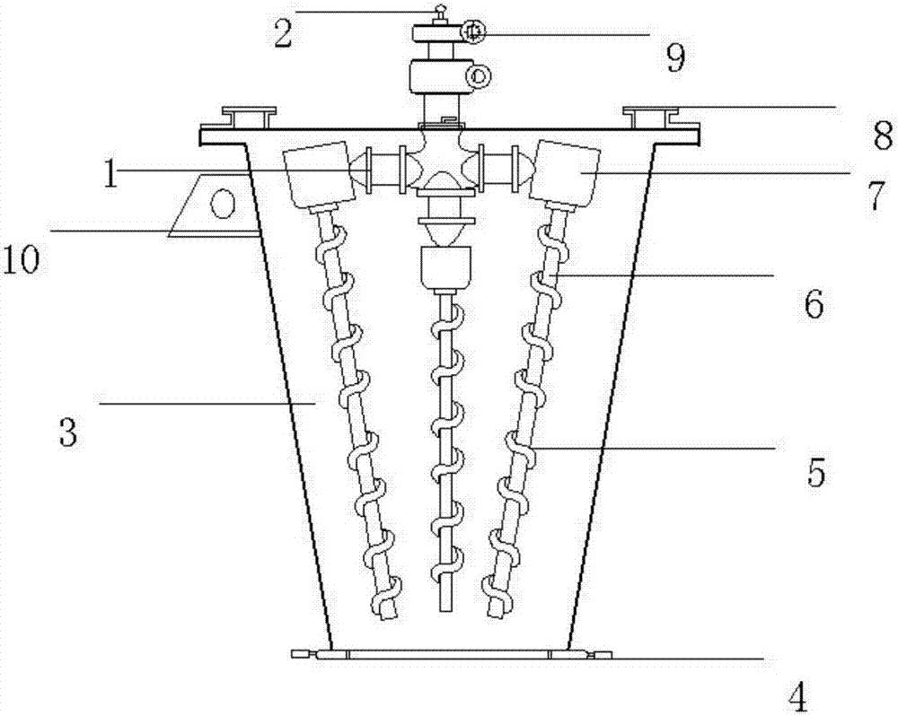
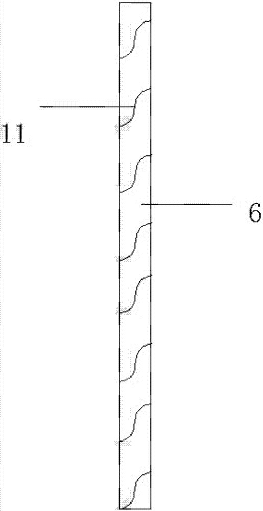
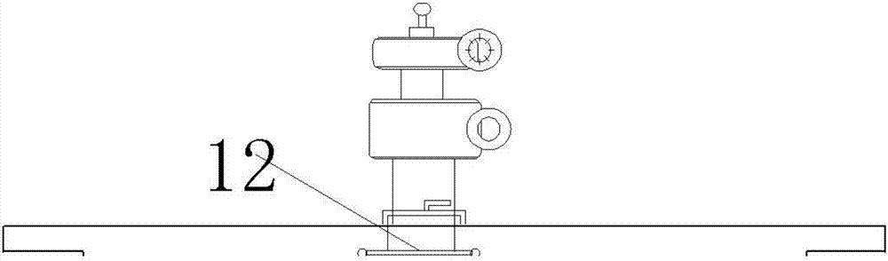
[0018] A mixer, characterized in that its structure includes a cylinder 3, a discharge valve 4, a screw blade 5, a rotating head 7, a rotating arm 1 and a reducer 9, and the cylinder 3 is connected to the rotating arm 1 , the rotating arm 1 is connected to the rotating head 7, the rotating head 7 is connected to the telescopic rotating shaft 6, the telescopic rotating shaft 6 is connected to the spiral blade 5, and the cylinder body 3 is connected to the liquid injection port 12 , the cylinder body 3 is connected with two feeding ports 8 and the reducer 9 , and the reducer 9 is connected with the liquid-feeding joint 2 . The surface of the telescopic rotating shaft 6 is provided with a card groove piece 11, the cylinder body 3 is connected with a switch button 11, the rotating head 7 is fixed to the telescopic rotating shaft 6 by screws, and the rotating arm 1 and the rotating head 7 joints are provided with grooves. The three-helix stirring device of the present invention ca...


PUM


Abstract

The invention discloses a mixer. The mixer comprises a cylinder, a discharge valve, spiral blades, rotating heads, a rotating arm and a speed reducer. The rotating arm is connected in the cylinder; the rotating arm is connected with the rotating heads; each rotating head is connected with a telescopic rotating shaft; each telescopic rotating shaft is connected with the corresponding spiral blade; the cylinder is connected with a liquid spray port; the cylinder is connected with two feed inlets and the speed reducer; and the speed reducer is connected with a charging connector. The three-screw stirring device provided by the invention can completely fully contact the materials and thoroughly mix the materials without dropping the materials on the bottom.

Description

technical field [0001] The invention relates to the field of chemical machinery, in particular to a mixer. Background technique [0002] The conical twin-screw mixer has wide adaptability to the mixed materials, will not overheat the heat-sensitive materials, will not feed and grind the granular materials, and will not cause segregation and segregation when mixing materials with different specific gravity and different particle sizes. [0003] The prior art discloses a conical double-screw mixer with the application number 201320275273.8, which includes a shell, the shell is conical, the inner wall of the shell is provided with spiral fins, and the top of the shell is provided with more than two feed pipes. The feed pipes are all tangent to the shell, the discharge end of the shell is a small tapered end, the discharge end is a steel discharge pipe, and a pneumatic valve is set on the discharge pipe; the spiral blades are two layers parallel to each other. , the spiral piec...

Claims


Application Information

Patent Timeline
Patent Type & Authority Applications(China)
IPC IPC(8): B01F7/30
CPCB01F27/191B01F27/953
Inventor 韩佳
Owner 天津日禾餐饮管理服务有限公司
Why Eureka
Try Eureka