Locking device for article surveillance

A technology for locking devices and products, which is applied to anti-theft alarms, electric alarms, instruments, etc., can solve the problems that anti-theft devices cannot be unlocked smoothly and the application range is limited, and achieve simple structure, improved service life, and simple assembly Effect

Pending Publication Date: 2017-11-24
XUZHOU DRAGON GUARD IND CO LTD
View PDF8 Cites 5 Cited by
  • Summary
  • Abstract
  • Description
  • Claims
  • Application Information

AI Technical Summary

Problems solved by technology

[0004] The purpose of the present invention is to provide a locking device for anti-theft of goods, to solve the problem that the existing anti-theft device cannot be unlocked smoothly when the connecting unit of the goods extends out of the locking mechanism, and the application range is limited

Method used


Image

  • Locking device for article surveillance
  • Locking device for article surveillance
  • Locking device for article surveillance

Examples


Embodiment 1

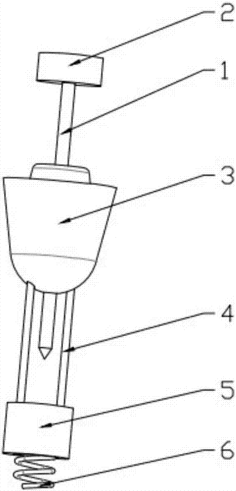
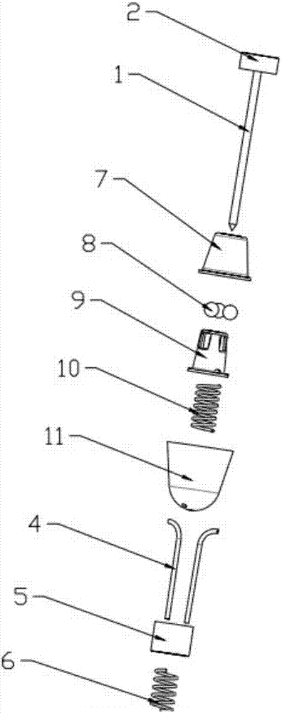
[0057] see Figure 1~3 , the locking device for commodity anti-theft includes a locking housing 3, a locking ball 8, a telescopic body 9, a locking return spring 10, a commodity connection unit, a traction body 5 and a sliding steel wire 4, and the upper part of the locking housing 3 The inner cavity is a locking cavity 12, and the cross section of the locking cavity 12 is trapezoidal; a plurality of locking balls 8 are arranged in the locking cavity 12; The lower side of the ball 8 and the upper part of the telescopic body 9 are provided with a locking ball holding mechanism; the locking return spring 10 is arranged inside the locking housing 3 on the lower side of the telescopic body 9; the slender commodity connection unit vertically passes through the locking Housing 3 and telescopic body 9, a plurality of locking balls 8 are evenly arranged around the commodity connection unit; traction body 5 is arranged under the locking housing 3 and is installed in the anti-theft hous...

Embodiment 2

[0063] see Figure 5 , The commodity connection unit includes an anti-theft steel wire 13, the upper end of the anti-theft steel wire 13 is a fixed end 14 relatively fixed to the locking housing 3, and the lower end is a free end 15. The fixed end 14 of the anti-theft steel wire 13 can be fixedly connected with the locking housing 3 to the anti-theft housing and the anti-theft housing.

[0064] The fixed end 14 of the anti-theft steel wire 13 is fixedly connected with a columnar body 16 , and the diameter of the columnar body 16 is larger than that of the anti-theft steel wire 13 . Two sliding steel wires 4 respectively pass through the locking housing 3 from both sides of the commodity connection unit, and the upper ends of the two sliding steel wires 4 are respectively connected to both sides of the telescopic body 9 . The directional sliding of the telescopic body 9 is guaranteed, and the work is stable and reliable. Other structures are the same as in Embodiment 1.

Embodiment 3

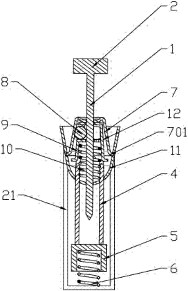
[0066] see Figure 6~7 , the locking housing 3 , the traction body 5 and the sliding steel wire 4 are all fixed inside the anti-theft housing 21 , and the commodity connection unit passes through the anti-theft housing 21 and the locking housing 3 .

[0067] In this embodiment, the commodity connecting unit is an anti-theft steel wire 13 as an example for illustration. The inside of the anti-theft housing 21 is provided with a fixed cavity for accommodating a columnar body 16, and the columnar body 16 of the anti-theft steel wire 13 is fixed in the fixed cavity. The two side walls of anti-theft housing 21 are provided with steel wire entrance and steel wire outlet respectively, and the free end 15 of anti-theft steel wire 13 penetrates in the anti-theft housing 21 by steel wire entrance and stretches out by steel wire outlet, and anti-theft steel wire 13 is in anti-theft housing 21. The inner side passes through the locking housing 3 and the telescopic body 9 at the same time....


PUM


Abstract

The invention relates to a locking device for article surveillance. The locking device comprises a locking shell, a plurality of locking balls, a telescopic body, a locking and resetting spring, an article connecting unit, a traction body and sliding steel wires, an upper inner cavity of the locking shell is a locking cavity, the section of the locking cavity is in a trapezoidal shape, the locking balls are arranged in the locking cavity, the telescopic body is arranged in the locking shell in a lifting manner and positioned on the lower side of the locking balls, a locking ball holding mechanism is arranged on the upper portion of the telescopic body, the locking and resetting spring is arranged in the locking shell of the lower side of the telescopic body, the article connecting unit vertically penetrates the locking shell and the telescopic body, the locking balls are uniformly arranged on the periphery of the article connecting unit, the traction body is provided with a magnet or an iron block and arranged in an antitheft shell, the upper ends of the sliding steel wires penetrate the locking shell and are fixedly connected with the telescopic body, and the lower ends of the sliding steel wires are connected with the traction body. According to the locking device, the traction body and the sliding steel wires drive the telescopic body to move, remote unlocking is achieved, and the locking device is applicable to articles with various specifications.

Description

technical field [0001] The invention relates to the field of anti-theft technology, in particular to a locking device for anti-theft commodities. Background technique [0002] With the rapid development of society and economy, there are more and more shopping malls and supermarkets, and the scale is getting bigger and bigger. The anti-theft of goods in shopping malls and supermarkets is an important part of their operations. In order to reduce labor costs and improve customer experience, at present Shopping malls and supermarkets mostly use anti-theft tags to lock on the goods, so as to prevent the goods from being maliciously stolen. [0003] Korean Utility Model No. 20-0274007 discloses a locking device for anti-theft goods, and Japanese Patent Application No. 2008-204218 discloses an anti-theft label. In an anti-theft case, a return spring is provided on the underside of the anti-theft case, and a plurality of steel balls arranged in a circular direction are arranged on ...

Claims


Application Information

Patent Timeline
Patent Type & Authority Applications(China)
IPC IPC(8): G08B13/24
CPCG08B13/2417G08B13/2434
Inventor 杨天莹
Owner XUZHOU DRAGON GUARD IND CO LTD
Why Eureka
Try Eureka