Rotor core

A rotor core and rotor technology, applied in the direction of magnetic circuit rotating parts, magnetic circuit shape/style/structure, electromechanical devices, etc., can solve the problems of increasing the volume of the rotor plate, and achieve improved driving range, good mechanical strength, small mass effect

Active Publication Date: 2017-12-12
VOLKSWAGEN AG
View PDF4 Cites 3 Cited by
  • Summary
  • Abstract
  • Description
  • Claims
  • Application Information

AI Technical Summary

Problems solved by technology

However this means that the central opening in the rotor plate for the rotor shaft is reduced to the same extent and thus increases the volume of the rotor plate

Method used


Image

  • Rotor core
  • Rotor core
  • Rotor core

Examples


Embodiment Construction

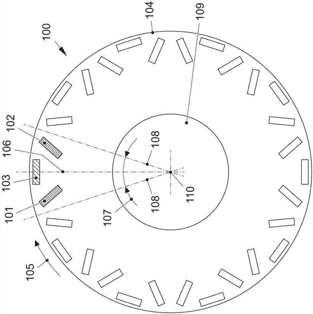
[0041] exist figure 1 Reference numeral 100 denotes a rotor core which serves as the basis for the embodiments of the invention explained below. The rotor core 100 is presented in an axial view, that is to say a view in the direction of the axis of rotation 110 of the rotor core 100 and thus in the direction of the rotor of the permanent magnet excited electric machine on which the rotor core is formed. The rotor core 100 here has, for example, ten magnetic poles. For each magnetic pole of the rotor core 100 or of the rotor formed of the rotor core, three permanent magnets 101, 102, 103 are provided, wherein two permanent magnets 101, 102 are arranged in a V-shaped configuration towards the rotor outer surface 104, ie Open radially outwards, and the third permanent magnet 103 is tangentially along the circumferential direction 105 and thus along the rotor outer surface 104 of the rotor core 100 at least almost centrally with respect to the radial center axis 106 of the V-shap...


PUM


Abstract

The present invention relates to a magnetically conductive rotor core (100) of a permanent magnet-excited rotor of a motor having three permanent magnets per pole, of which two permanent magnets are arranged in a V (V) open towards the outer rotor surface (104) (101, 102) and the third permanent magnet (103) is arranged tangentially in the circumferential direction (105) of the rotor core (100). For each pole a set of pockets is provided in the rotor core. Each set of recesses comprises a large recess (111; 122; 131; 142) and at least three small recesses (115,116,117,118,119,120,121; 127,128,129,130; 136,137 , 138, 139, 140, 141; 144) which adjoins the borders of the large recesses in a honeycomb pattern (112,113; 123,124,125; 132,133,134; 143). The radial cross-sectional area of the large recess is at least twice the radial cross-sectional area of each small recess. This results in a weight saving with higher mechanical strength.

Description

technical field [0001] The invention relates to a rotor core. The invention also relates to a rotor with such a rotor core, an electric machine with such a rotor and a vehicle with such an electric machine. Background technique [0002] A rotor for an electric machine is known from WO 2005 / 117235 A1. The rotor includes a magnetically conductive rotor plate on a rotor shaft. Permanent magnets are inserted in the rotor plate, which are each oriented towards both sides of the magnetic poles in the radial direction of the rotor and in the direction of rotation. In each pole, the permanent magnets are arranged axially of the rotor in a V-shaped configuration which opens towards the outer surface of the rotor, ie radially outwards. In addition to the central opening for the rotor shaft, the rotor plate also has a large number of other openings, through which the rotor construction is made lighter. These other openings are arranged radially between the permanent magnets and the...

Claims


Application Information

Patent Timeline
Patent Type & Authority Applications(China)
IPC IPC(8): H02K1/27
CPCH02K1/27H02K1/2766
Inventor S.罗思M.塔舍
Owner VOLKSWAGEN AG
Why Eureka
Try Eureka