Side-nail anastomat

A stapler and side staple type technology, applied in the field of side staple staplers, can solve the problems of incomplete anastomosis, inability to approach the foreskin, tissue residue, etc., and achieve the effects of easy anastomosis, easy anastomosis, and easy confirmation.

Pending Publication Date: 2018-01-09
SURGAID MEDICAL XIAMEN CO LTD
View PDF0 Cites 0 Cited by
  • Summary
  • Abstract
  • Description
  • Claims
  • Application Information

AI Technical Summary

Problems solved by technology

[0004] The existing cutting staplers all use vertical cutting and vertical nails. The way of vertical nailing will make the position of the stapler unable to be close to the joint between the foreskin and the glans. , there will be an incomplete fit

Method used


Image

  • Side-nail anastomat
  • Side-nail anastomat
  • Side-nail anastomat

Examples


Embodiment 1

[0035] Such as Figure 2-10 As shown: the functional part also includes a cutter assembly, the cutter assembly is a side-cut cutter assembly, and the side-cut cutter assembly includes a cutter push rod 41, a locking member 42, and a cutter 43;

[0036] The cutter push rod 41, the locking member 42, and the cutter 43 are sequentially connected and arranged on the side wall of the cutter housing group 21, and the cutter push rod 41 extends out of the cutter housing group 21;

[0037] The pushing structure includes a lower movable ring 51, several groups of pins 52 and a nail limiting plate 56 connected with the handle; an annular opening is arranged on the lower wall of the wheel shell group 21 and the periphery of the handle 11, and the lower movable ring 51 is embedded in the annular opening, and rotates with cutting wheel shell group 21, is provided with protruding guide rail 54 on the upper wall surface ring of lower movable ring 51; There are nail holes 57; the pins 52 are...

Embodiment 2

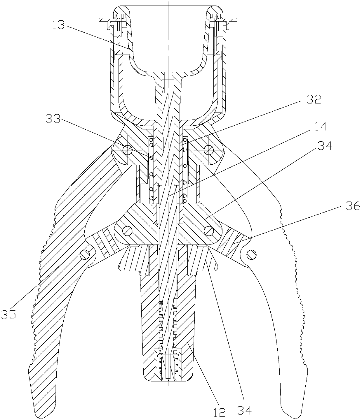
[0043] Such as Figure 11-12 As shown: the above also includes a cutter assembly, which is a vertical cutter assembly, which includes a push knife cover 31, a connecting rod 32, a return spring 33, a push slider 34, a movable handle 35, and a handle connector 36;

[0044] The push knife cover 31 is a cover-like structure with a blade on the front edge, and the push knife cover 31 is located at the periphery of the glans cover 13. The push knife cover 31 is connected to the front end of the connecting rod 32, and the pushing slider 34 is connected to the tail end of the connecting rod 32, and the pushing slider 34 extends out of the handle 11 through the opening provided on the side wall of the handle 11, the front end of the movable handle 35 is hinged on the side wall of the front part of the handle 11, and several limit connecting rods 37 extend from the side wall of the handle 11. The front end of the rod 37 is provided with a position-limiting protrusion 38, and an annula...


PUM


Abstract

The invention relates to a side staple type stapler. It includes a hand-held part and a functional part; the hand-held part includes a handle and a glans cover that is arranged at the front end of the glans cover and can move back and forth; the functional part includes a side nail assembly, and the side nail assembly includes a cutting wheel shell group, a pushing block, a pushing structure and The ring is equipped with a number of nail magazines with nail channels; the cutting wheel shell group is rotatably connected to the front part of the handle, and the nail magazine is in the shape of a ring. The pushing structure is located under the staple bin and the pushing structure is connected to the cutting wheel shell group; staples and pushing blocks are arranged in the nail setting channel from inside to outside, and a pushing slope is provided on the inner cavity wall of the cutting wheel shell group. The advantages of the present invention are: 1. When the stapled position is close to the joint between the foreskin and the glans and the circumcision is close to the stapled position, the effect of cutting the foreskin is the best; 2. Cutting and anastomosis from the side of the tissue can be more effective. Good to avoid tissue residue, easier to confirm the anastomosis phenomenon, easier anastomosis.

Description

technical field [0001] The invention relates to a medical device, in particular to a side staple stapler. Background technique [0002] The existing traditional cutting stapler is used in the way of vertical cutting and vertical nailing, that is, the direction of cutting and stapling is parallel to the head end of the product, but there are still some defects; [0003] Circumcision surgery is to remove the foreskin tissue extending outward from the junction of the foreskin and the glans. That is to say, the closer the incision of the removed foreskin is to the junction of the foreskin and the glans, the better the effect. This generally depends on two factors. The first factor is the position of the staples. The closer the position is to the junction of the foreskin and the glans, the better the circumcision effect is. The second factor is the position of the circumcision. The closer the position is to the staples. The closer, the better. [0004] The existing cutting stap...

Claims


Application Information

Patent Timeline
Patent Type & Authority Applications(China)
IPC IPC(8): A61B17/326A61B17/115
Inventor 莫易凡林志雄林聪杰邱木旺胡林锋
Owner SURGAID MEDICAL XIAMEN CO LTD
Why Eureka
Try Eureka