Automatic stamping system and method applicable to stainless steel cylinder parts of different sizes

A technology of cylindrical parts and stainless steel, which is applied in the field of automatic stamping systems, can solve the problems of complex process and low production efficiency of non-standard stainless steel cylinders, and achieve the effect of quality assurance

Inactive Publication Date: 2018-01-09
巴中市新越不锈钢有限公司
View PDF8 Cites 3 Cited by
  • Summary
  • Abstract
  • Description
  • Claims
  • Application Information

AI Technical Summary

Problems solved by technology

[0003] The purpose of the present invention is to overcome the deficiencies of the prior art. The purpose is to provide an automatic stamping system and method suitable for stainless steel cylinders of different sizes, so as to solve the problems of low production efficiency and complicated process of non-standard stainless steel cylinders.

Method used


Image

  • Automatic stamping system and method applicable to stainless steel cylinder parts of different sizes

Examples


Embodiment 1

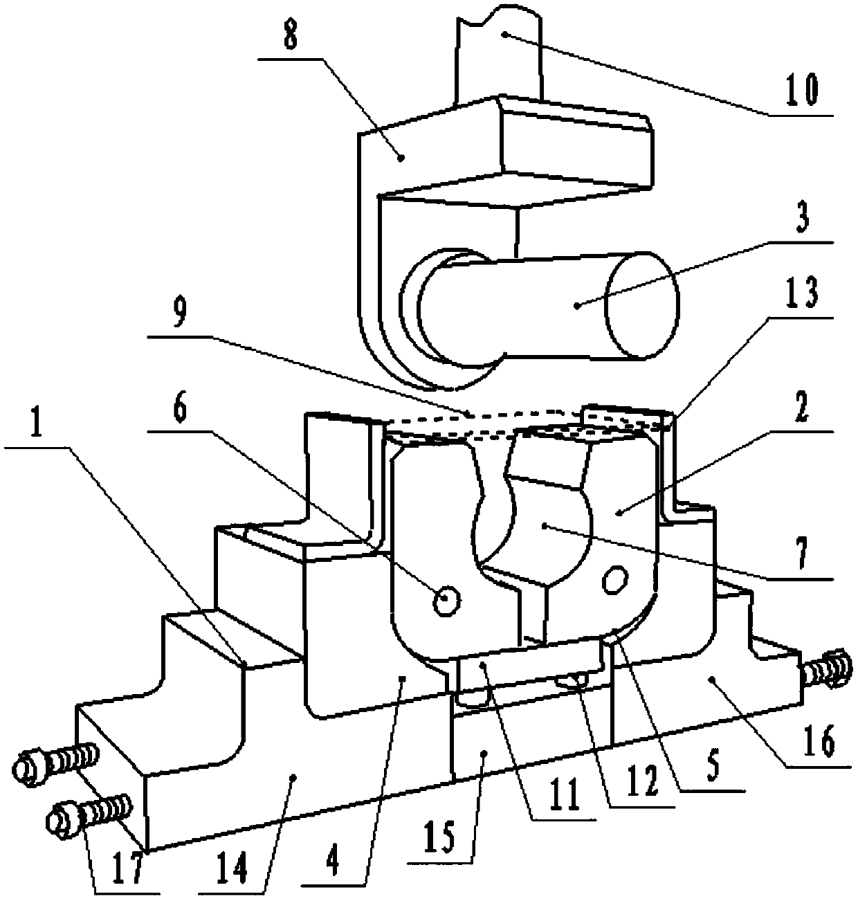
[0036] Such as figure 1 As shown, the present invention is an automatic stamping system suitable for stainless steel cylinders of different sizes, including a stamping base 1, a stamping female module 2 and a stamping male die rod 3, and the stamping base 1 includes a left stamping base 14, a middle stamping base 15 and The right stamping base 16, the left stamping base 14 and the right stamping base 16 are respectively connected with the middle stamping base 15 through the adjusting screw 17;

[0037] The middle stamping base 15 of the stamping base 1 is symmetrically provided with two stamping limit blocks 4, and the inner surfaces of the left stamping base 14 and the right stamping base 16 are all provided with a limiting arc surface 5, and the two stamping The female module 2 is correspondingly arranged on the limiting arc surface 5 of the left stamping base 14 and the right stamping base 16 through the limiting shaft 6; camber 7;

[0038] The stamping male mold rod 3 is...

Embodiment 2

[0052] Such as figure 1 As shown, the present invention is an automatic stamping method applicable to stainless steel cylindrical parts of different sizes, comprising steps:

[0053] Step 1) Adjust the distance between the left stamping base (14) and the middle stamping base (15); the distance between the right stamping base (16) and the middle stamping base (15) by adjusting the screw rod (17);

[0054] Step 2) After the size adjustment of the stamping base (1) is completed, place the cut stamping plate (9) between the two L-shaped stamping plates (13) stoppers;

[0055] Step 3) Then, the punching bed drives the punching arm (10) to punch downwards, and the punching arm (10) drives the punching male die rod (3) to punch the punching plate (9);

[0056] Step 4) Stamping the male mold rod (3) by inserting the stamping plate (9) into the two stamping female modules (2) to form a cylindrical mold, and under the stamping action of the stamping male mold rod (3), the stamping fema...


PUM


Abstract

The invention discloses an automatic stamping system and method applicable to stainless steel cylinder parts of different sizes. The automatic stamping system and method applicable to stainless steelcylinder parts of different sizes comprises a stamping base, stamping female die blocks and a stamping male die stick. The stamping base comprises a left side stamping base, a middle stamping base anda right side stamping base. The left side stamping base is connected with the middle stamping base through adjusting threaded rods. The right side stamping base is connected with the middle stampingbase through adjusting threaded rods. Two stamping limiting blocks are symmetrically arranged on the middle stamping base of the stamping base. A limiting cambered surface is arranged on the inner face of the left side stamping base. A limiting cambered surface is arranged on the inner face of the right side stamping base. The two stamping female die blocks are arranged on the limiting cambered surface of the left side stamping base and the limiting cambered surface of the right side stamping base correspondingly through limiting shafts. An arc surface matched with the excircle of a stamping cylinder part is arranged on the inner face of each stamping female die block. The stamping male die stick is horizontally arranged above corresponding to the stamping base and movably connected with astamping block. The stamping male die stick makes a plate to be stamped go into the cylinder die formed by the two stamping female die blocks, and under the stamping action of the stamping male die stick, the stamping female die blocks turn around the respective limiting shafts to make the plate to be stamped form a cylinder part in a stamping manner.

Description

technical field [0001] The invention relates to the field of mechanical processing stamping manufacturing, in particular to an automatic stamping system and method applicable to stainless steel cylindrical parts of different sizes. Background technique [0002] In the field of hardware manufacturing, many heterosexual parts need to be stamped and manufactured. At present, in the process of making non-standard stainless steel cylinders, the plates are cut into materials of certain specifications according to needs, and then, manually or with the help of some simple After the mold is made into a cylindrical shape, it is welded by electric welding. In this way, the quality of the workpiece cannot be guaranteed, and its production efficiency cannot be improved. Therefore, it is necessary to improve it. Contents of the invention [0003] The purpose of the present invention is to overcome the deficiencies of the prior art, to provide an automatic stamping system and method suit...

Claims


Application Information

Patent Timeline
Patent Type & Authority Applications(China)
IPC IPC(8): B21D5/10B21D43/00
Inventor 吕红清
Owner 巴中市新越不锈钢有限公司
Why Eureka
Try Eureka