Sliding rail mechanism suitable for adjusting roller shutters of household doors and windows
What is Al technical title?
Al technical title is built by PatSnap Al team. It summarizes the technical point description of the patent document.
A technology for rolling shutters and doors and windows, applied in door/window protection devices, windows/doors, building components, etc., can solve the problems of easy-to-lock, inconvenient adjustment, and inability to achieve automatic winding, and reduce the foundation cost effect
Inactive Publication Date: 2018-03-13
泉州市诚京贸易有限公司
View PDF0 Cites 0 Cited by
Summary
Abstract
Description
Claims
Application Information
AI Technical Summary
This helps you quickly interpret patents by identifying the three key elements:
Problems solved by technology
Method used
Benefits of technology
Problems solved by technology
[0005] (1) The roller shutter mechanism in the prior art is a mechanism for up and down adjustment, and its adjustment method adopts columnar or rod-shaped rotation adjustment. In the actual application process, the adjustment method is not very convenient, and it is easy for the card owner to appear question
[0006] (2) In the prior art, most of the roller shutter mechanisms are manually adjusted, and functions such as automatic winding cannot be realized
Method used
Image
Click on the blue label to locate the original text in one second.
Reading with bidirectional positioning of images and text.
Examples
Embodiment
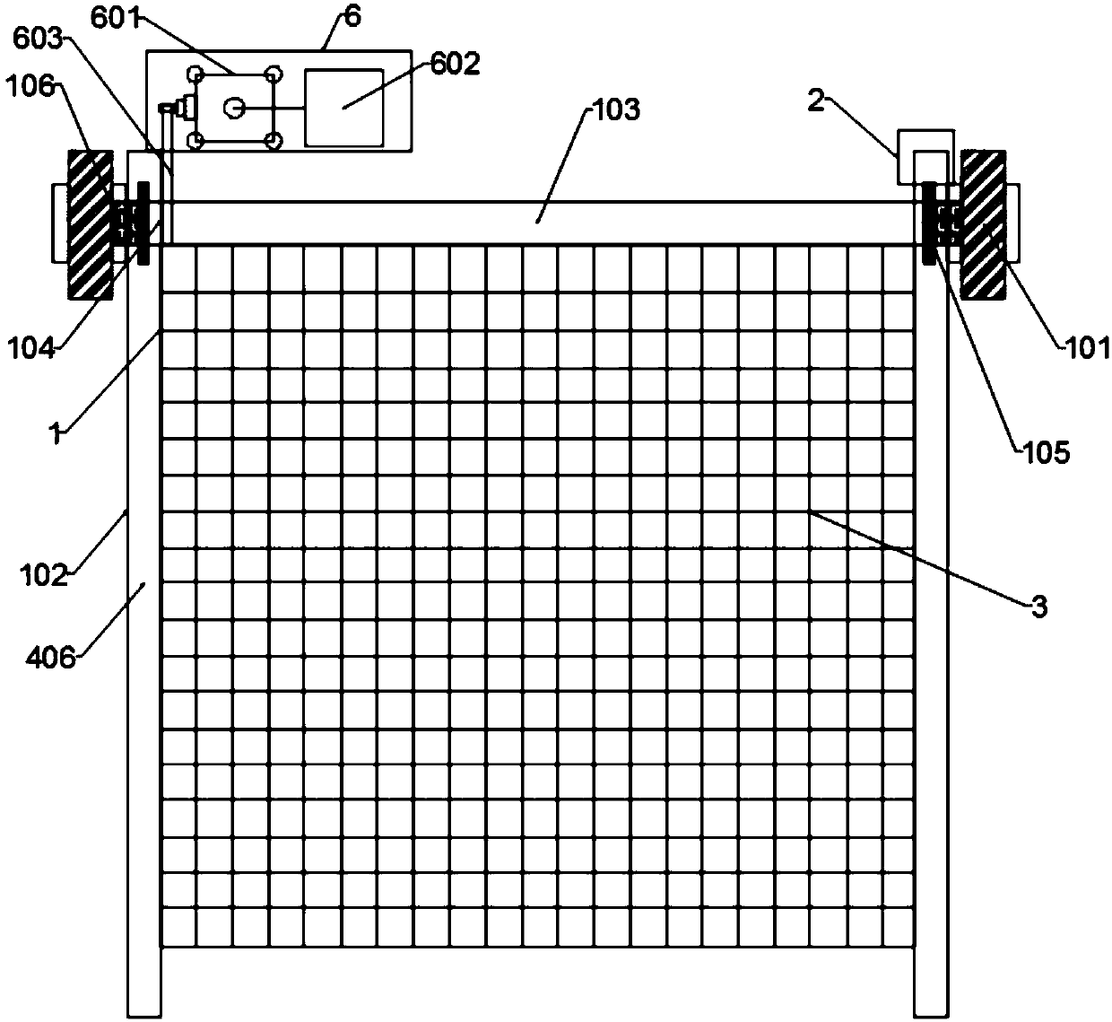
[0046] Such as figure 1 As shown, the present invention provides a roller shade manual drive device 5 that includes a roller shade support main body mechanism 1, a roller shade clutch device 2, and is connected to the roller shade clutch device 2, and an automatic roller blind drive device installed above the roller shade support main body mechanism 1. device6.
[0047] The present invention mainly controls the rolling blind clutch device 2 through the manual driving device 5 of the rolling blind, thereby realizing the manual control of the parts of the main body mechanism 1 of the rolling blind to achieve the purpose of controlling the curtain, and the automatic driving device 6 of the rolling blind through the intelligent The circuit module is used to control the internal components of the roller blind supporting main body mechanism 1, and realize the function of remote control and automatic control of the curtain.
[0048] Such as figure 1 As shown, the main body mechanis...
PUM
Abstract
The invention discloses a sliding rail mechanism suitable for adjusting home door and window roller blinds. The slide rail baffle, a track is formed between the two slide rail baffles, the inner side of the slide rail baffle is provided with a ball fixing cavity, and the ball fixing cavity is movable and equally spaced to accommodate balls. Hemispherical rolling cavity, the two ends of the longitudinal adjustment plate and the horizontal adjustment plate are respectively installed in the track, and the upper and lower sides of the longitudinal adjustment plate and the horizontal adjustment plate are in contact with the balls, and the upper and lower sides of the longitudinal adjustment plate and the horizontal adjustment plate are in contact with the balls. Both sides are in contact with the balls, and through the free rotation of the balls in the hemispherical rolling cavity, the horizontal adjustment plate and the longitudinal adjustment plate installed between the slide rail baffles can slide freely.
Description
technical field [0001] The invention relates to the technical field of home door and window roller blinds, in particular to a slide rail mechanism suitable for adjusting home door and window roller blinds. Background technique [0002] Curtains are made of cloth, hemp, yarn, aluminum flakes, wood chips, metal materials, etc., and have the functions of sunshade and heat insulation and adjusting indoor light. Non-woven fabrics, etc., different materials, textures, colors, patterns, etc. are combined to form different styles of curtains, which match different styles of interior design curtains. The control mode of the curtain is divided into manual and electric. Manual curtains include: manual opening and closing curtains, manual bead roller blinds, manual silk curtains, manual wooden blinds, manual Roman blinds, manual organ curtains, etc. Electric curtains include: electric opening and closing curtains, electric roller blinds, electric silk curtains Venetian blinds, electri...
Claims
Application Information
Patent Timeline
Application Date:The date an application was filed.
Publication Date:The date a patent or application was officially published.
First Publication Date:The earliest publication date of a patent with the same application number.
Issue Date:Publication date of the patent grant document.
PCT Entry Date:The Entry date of PCT National Phase.
Estimated Expiry Date:The statutory expiry date of a patent right according to the Patent Law, and it is the longest term of protection that the patent right can achieve without the termination of the patent right due to other reasons(Term extension factor has been taken into account ).
Invalid Date:Actual expiry date is based on effective date or publication date of legal transaction data of invalid patent.