Individual drive for detaching rollers of a combing machine

A technology for separating rollers and combers, which is used in combers, textiles and papermaking, fiber processing, etc., can solve the problems of complex and expensive layout, and achieve the effect of reducing quality

Inactive Publication Date: 2018-03-23
MASCHINENFABRIK RIETER AG
View PDF14 Cites 1 Cited by
  • Summary
  • Abstract
  • Description
  • Claims
  • Application Information

AI Technical Summary

Problems solved by technology

So in some cases smaller motors can be used, bu

Method used


Image

  • Individual drive for detaching rollers of a combing machine
  • Individual drive for detaching rollers of a combing machine
  • Individual drive for detaching rollers of a combing machine

Examples


Embodiment Construction

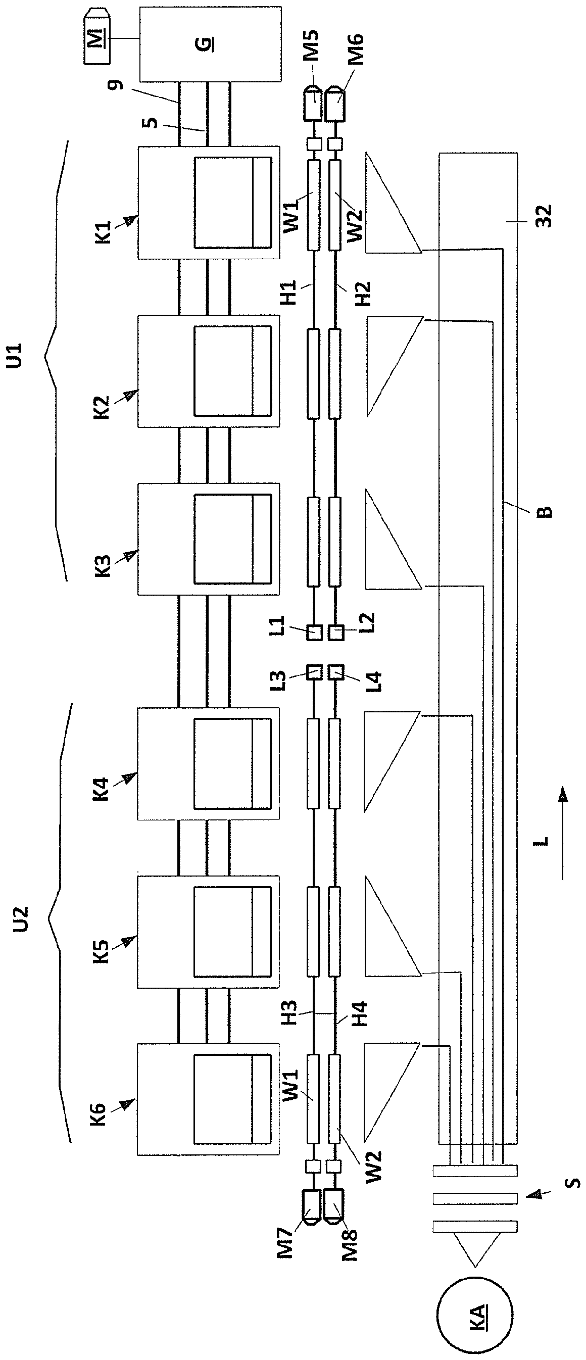
[0024] figure 1 A known embodiment of a combing head (s) K1 of a combing machine is shown, which has a pincer unit 1 (referred to simply as "pincer") which is mounted so that it can be moved by means of crank arms 2, 3. pivotally move. The two crank arms 2 are respectively mounted pivotably on their shaft 5 on the sides of the cylinder comb (also called "circular comb"). The other end of the pivot arm 2 is attached to a lever shaft 13 on the jaw frame 8 so as to be rotatably movable. The rear pivot arm 3 (possibly two) is mounted in a rotatably fixed mount on the tong shaft 10 . The opposite free end of the pivot arm 3 is connected to the jaw frame 8 so as to be rotatably movable by a shaft 9 .

[0025] The combing cylinder 4 has on a part of its circumference a combing section 7 which, as schematically shown, is provided with a combing card clothing and is driven in the direction of rotation D. As shown in FIG.

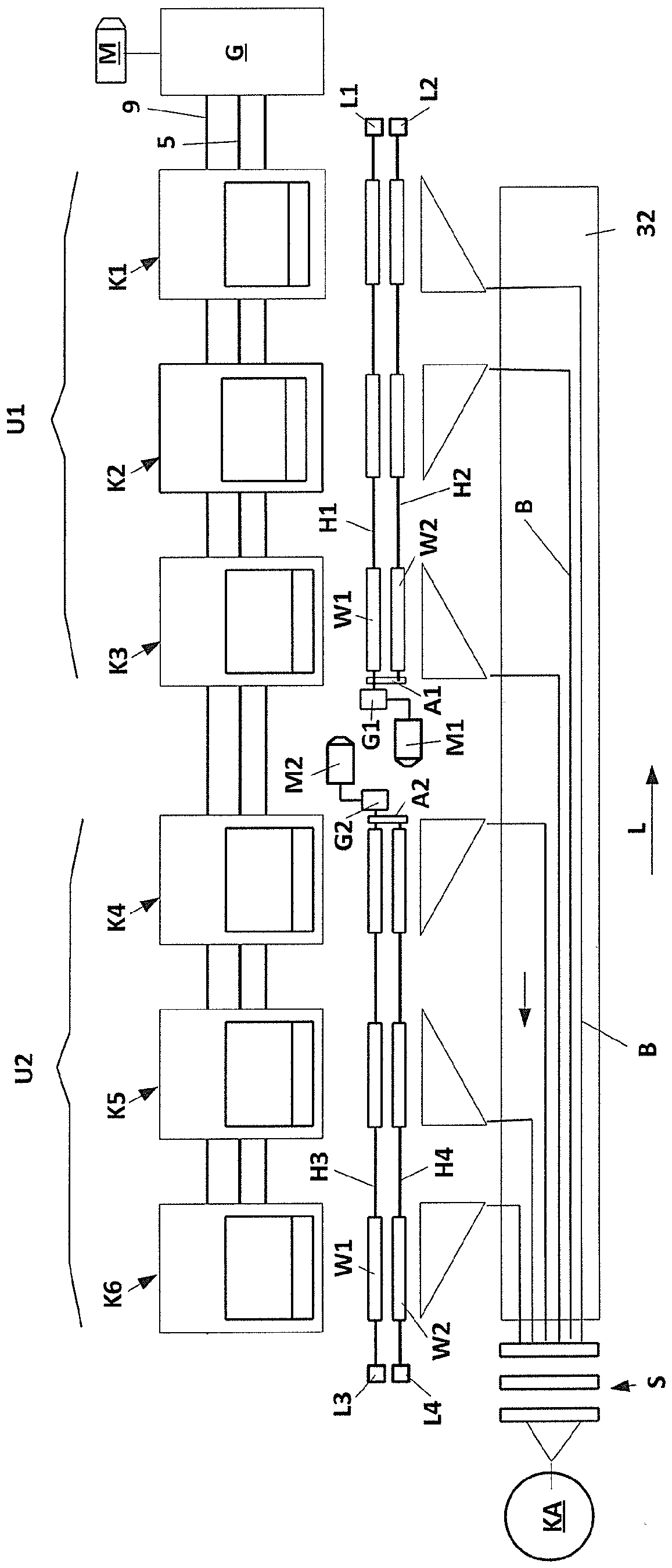
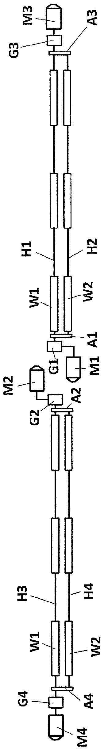
[0026]In this example, the pliers 1 comprise a lower nipper...


PUM


Abstract

The invention relates to a combing machine comprising at least one group of adjacently arranged combing heads (K1 to K6). The slivers (B) formed on each combing head are fed to a stretching unit (S) on a subsequent conveyor element (32). Each of the combing heads is provided with a nipper assembly (1) which pivots back and forth and with a rotatably mounted combing cylinder (4), and each combing head has two rotatably mounted detaching roller pairs (24, 25), which are arranged one behind the other when seen in the transport direction (F) of the fiber material (W). The drive shafts (H1, H2) ofthe detaching roller pairs extend over multiple combing heads (K1-K6) and carry out a pilgrim step movement during a combing operation, and at least one end of at least one of the detaching roller pairs (24, 25) is driven by at least one electric motor (M1, M2). The aim of the invention is to simplify the electromotive drives of the detaching rollers and to reduce the mass to be accelerated. Thisis achieved in that at least two groups (U1, U2) of adjacently arranged combing heads (K1-K6) are provided, and each of the groups has separate drive shafts (H1 to H4) for the detaching roller pairs (24, 25), said drive shafts being driven by at least one electric motor (M1, M2) directly or indirectly via a transmission stage (G1, G2).

Description

technical field [0001] The invention relates to a combing machine with at least one group of combing heads arranged side by side, wherein the fiber sliver formed on the corresponding combing head is conveyed to a conveyor element downstream of the pulling unit, and each combing head is provided with a shuttle An oscillating nipper assembly and is provided with a rotatably mounted combing cylinder and two rotatably mounted pairs of detaching rollers, seen in the transport direction of the fiber material, arranged one behind the other, the drive shafts of which extend The reciprocating movement is performed by a plurality of combing heads and during a combing cycle, wherein at least one end of at least one of the detaching roller pairs is driven by at least one electric motor. Background technique [0002] In practice, today's customary combing machines usually have eight combing heads arranged side by side. The fiber material is fed in the form of a sliver to the respective ...

Claims


Application Information

Patent Timeline
IPC IPC(8): D01G19/20D01G19/26
CPCD01G19/20D01G19/26
Inventor F.富尔雷S.洛彻尔
Owner MASCHINENFABRIK RIETER AG
Why Eureka
Try Eureka