Voice coil wire bending fixture and bending method

A voice coil and wire technology, applied in the field of speaker production fixtures, can solve the problems of difficulty in unifying the sound performance of finished products, difficult to achieve a unified line shape, lack of production fixtures, etc., to reduce the rate of brain drain, single action, and frequency response curve. Consistent and stable effect

Active Publication Date: 2018-03-27
SHENGDIAN ELECTRONICS TECH HUIZHOU
View PDF5 Cites 0 Cited by
  • Summary
  • Abstract
  • Description
  • Claims
  • Application Information

AI Technical Summary

Problems solved by technology

[0004] In the current headphone speaker production process, the bending line of the voice coil wire is basically bent manually based on the experience of the workers, and it is difficult to achieve a unified (preset) line
Therefore, in the

Method used


Image

  • Voice coil wire bending fixture and bending method
  • Voice coil wire bending fixture and bending method
  • Voice coil wire bending fixture and bending method

Examples


Embodiment 1

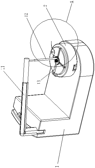
[0038] according to figure 1 , figure 2 , image 3 As shown, the voice coil wire bending jig in this embodiment includes a platform 1 and a wire bending base 2 .

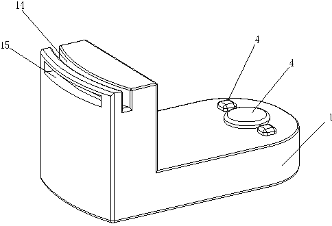
[0039] Such as Figure 4 As shown, a limiting groove 3 is provided at the bottom of the bending line base 2 , and a limiting protrusion 4 for being embedded in the limiting groove 3 is provided at the front of the platform 1 . The bending line base 2 is detachably placed on the front part of the bearing platform 1. Under the limited cooperation of the limiting groove 3 and the limiting protrusion 4, the bending line base 2 cannot rotate freely relative to the bearing platform 1, which is necessary for the subsequent bending line. Provide a unified space coordinate system and a relatively fixed bending line environment.

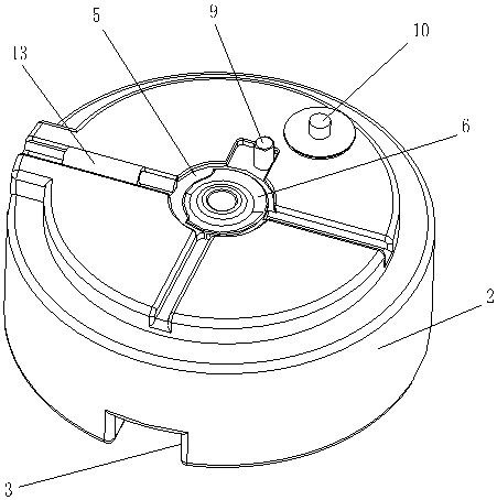
[0040] Such as Image 6 As shown, the diaphragm is composed of a diaphragm 7 and a copper ring 8 connected to the edge of the diaphragm 7 . A diaphragm placement area 5 is formed in a depress...

Embodiment 2

[0046] In order to unify the connection between the voice coil and the diaphragm and improve production efficiency, this embodiment is an improvement on the basis of Embodiment 1, as Figure 8 and Figure 9 As shown, it also includes a top cover 16 for pressing onto the bending wire base 2. On the inner cover surface of the top cover 16, there is an annular protrusion opposite to the center of the diaphragm tray 6 and used for connecting the voice coil 99. The top cover 16 is provided with a group of light-transmitting holes 18 around the circumference of the annular flange. A connecting groove 18 for connecting with the upper rotating shaft of the glue machine is formed in an upward depression on the bottom surface of the bending line base 2 .

[0047] When connecting the voice coil 99, the wire bending base 2 is first moved to the glue machine, and connected to the rotating shaft in the middle of the glue machine table through the connecting groove 18, and the wire bending ...

Embodiment 3

[0049] This embodiment provides a method for bending the voice coil wire 98 through the voice coil wire bending jig in the above embodiment, such as Figure 5 shown, including the following steps:

[0050] i. Place the diaphragm in the diaphragm tray 6 and glue the voice coil 99 to the center of the diaphragm. In this step, the diaphragm can be further pushed up and limited by the spring thimble mechanism 13 .

[0051] ii. Adjust the second winding post 12 to the preset position relative to the diaphragm. The adjustment in this step includes adjusting the position of the swing arm 11 in the groove-shaped raceway, as well as the height position of the second winding post 12 adjust.

[0052] iii. Bending the voice coil wire 98 around the second winding post 12 and the first winding post 9 in order to conform to the pre-wire design.

[0053] iv. The free end of the voice coil wire 98 is compressed and limited by the wire crimping block 10, and the bent voice coil wire 98 is bon...


PUM


Abstract

The invention relates to a voice coil wire bending fixture and a voice coil wire bending method. The fixture comprises a bearing platform and a wire bending pedestal can be placed in the front of thebearing platform, wherein the middle part of the top surface of the bending wire pedestal is sunk to form a vibrating diaphragm placement area in which a vibrating diaphragm tray is arranged, a firstwrapping post and a wire pressing block biased to one side of the vibrating diaphragm tray are arranged on the top surface of the wire bending pedestal, the rear part of the bearing platform is connected with a swinging support arm which can be vertically lifted or swung, a second wrapping post vertically extending downwards is connected with the front end of the swinging support arm, and when theswinging support arm is horizontally placed, the bottom end of the second wrapping post is closed to and suspended above the vibrating diaphragm tray. According to the voice coil wire bending fixtureand bending method provided by the invention, loudspeakers with the voice coil wires having unified curvature or linetype can be efficiently produced, the production efficiency is improved, and the product quality is ensured.

Description

technical field [0001] The invention relates to the field of loudspeaker production jigs, in particular to a voice coil wire bending jig and a bending method. Background technique [0002] Dynamic earphones are the most common and common earphones. Its drive unit is basically a small dynamic speaker, and the diaphragm (diaphragm) connected to it is driven by the voice coil in the permanent magnetic field to vibrate. Dynamic earphones have relatively high efficiency, and most of them can be driven by the earphone output on the audio system, and are reliable and durable. [0003] As we all know, after the voice coil is connected to the diaphragm, it is necessary to connect another piece of wire to the audio signal input terminal. This piece of wire is the voice coil wire. If the workmanship is not good, it will affect the normal performance of the speaker. In addition, because the voice coil wire needs to be bonded to the diaphragm by "dispensing glue", the bending shape of ...

Claims


Application Information

Patent Timeline
IPC IPC(8): H04R31/00
CPCH04R31/003H04R2231/003
Inventor 袁智杰郑雷温世龄张保明
Owner SHENGDIAN ELECTRONICS TECH HUIZHOU
Why Eureka
Try Eureka