A steel bar cutting device for construction engineering

A cutting device and construction engineering technology, which is applied in the field of steel bar cutting devices for construction engineering, can solve the problems of high labor intensity, sore arms of workers, time-consuming and labor-intensive problems, etc.

Active Publication Date: 2019-09-06
广东永基建筑基础股份有限公司
View PDF5 Cites 1 Cited by
  • Summary
  • Abstract
  • Description
  • Claims
  • Application Information

AI Technical Summary

Problems solved by technology

[0005] In order to overcome the disadvantages that the existing manual hand-held cutting machine cuts the steel bars used in construction engineering, the labor intensity is high, time-consuming and labor-intensive, and at the same time, the hand-held cutting machine for a long time will cause the staff's arm to be sore. The technical problem to be solved by the invention It is to provide a steel bar cutting device for construction projects that has low labor intensity, saves time and effort, and does not cause sore arms of the staff

Method used


Image

  • A steel bar cutting device for construction engineering
  • A steel bar cutting device for construction engineering
  • A steel bar cutting device for construction engineering

Examples


Embodiment 1

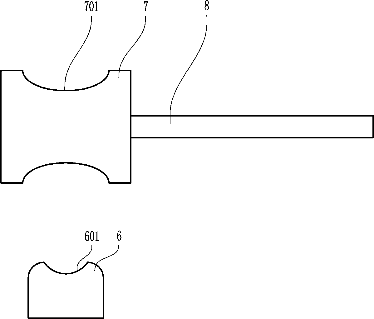
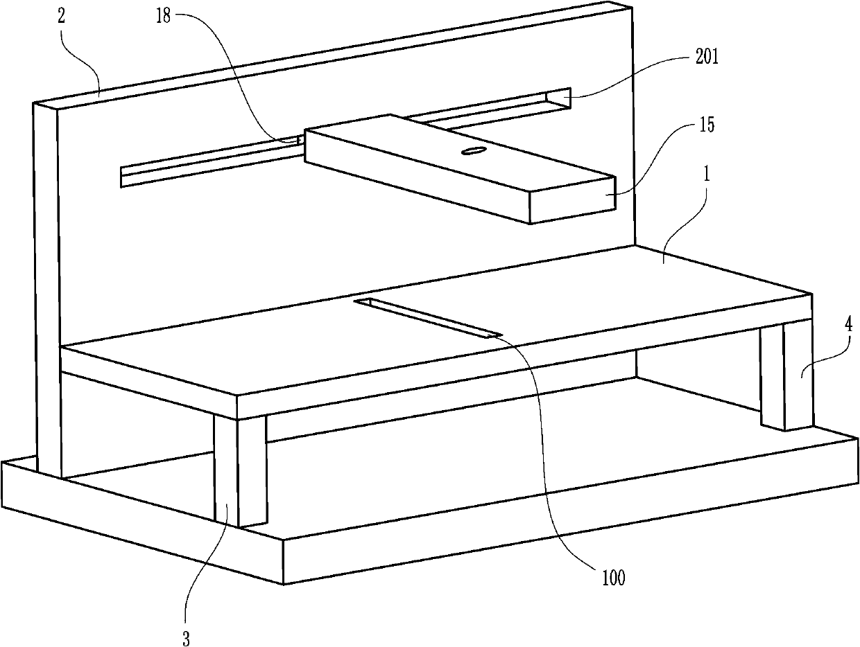
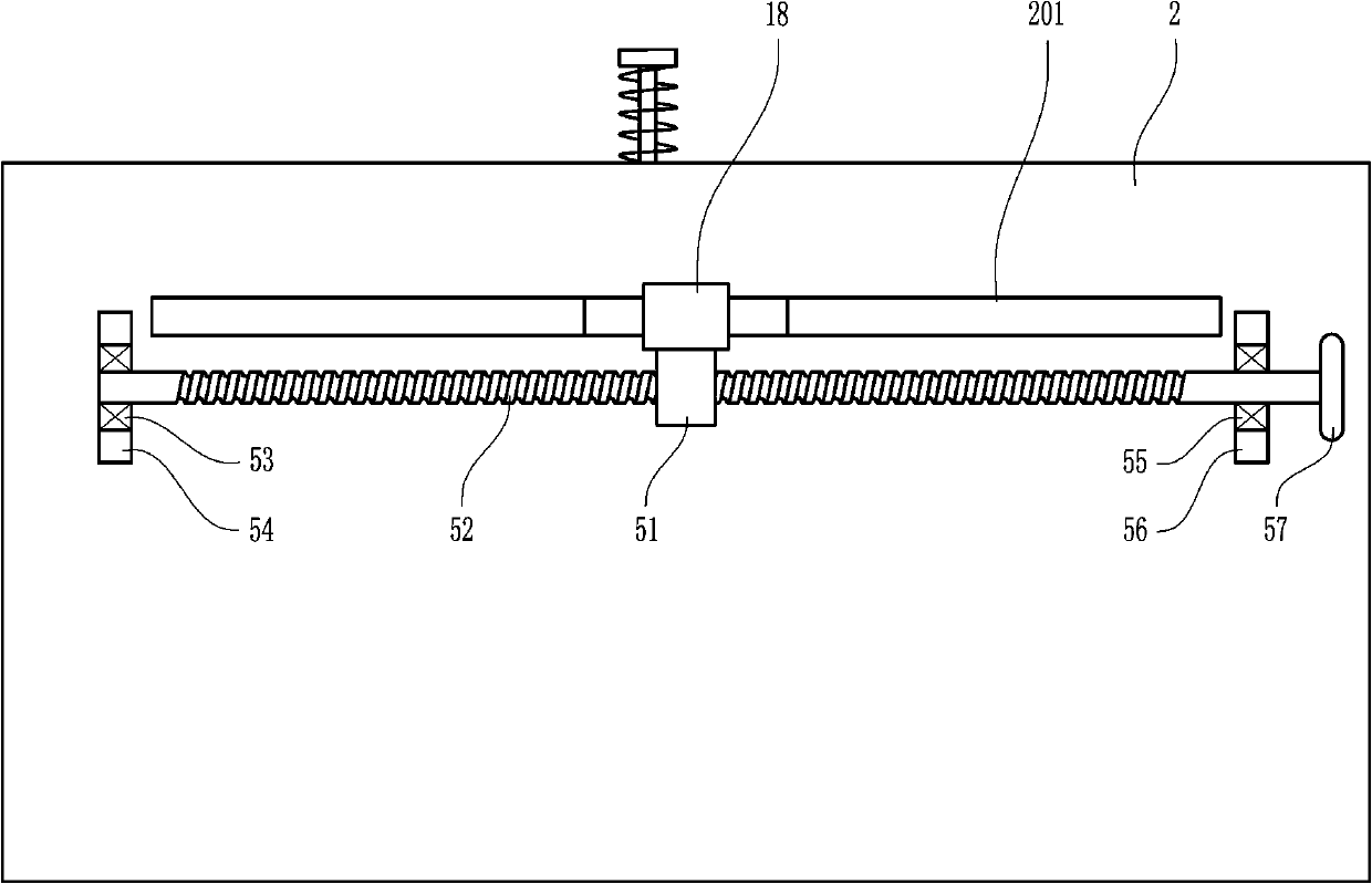
[0030] A steel bar cutting device for construction engineering, such as Figure 1-8 As shown, it includes a workbench 1, a large fixed plate 2, a first leg 3, a second leg 4, a base 5, a first fixed block 6, a first pressure roller 7, a first connecting shaft 8, a first rectangular Guide rod 9, first guide plate 10, supporting plate 11, extension spring 12, cutting machine 13, long guide rod 14, movable plate 15, stopper 16, spring 17 and T-shaped slide block 18, the rear side of workbench 1 The wall is connected with the front side wall of the large fixed plate 2, the left end of the bottom of the workbench 1 is connected with the first leg 3, the right end of the bottom of the workbench 1 is connected with the second leg 4, and the base 5 is located at the large fixed plate 2, the first leg 3 Below one leg 3 and the second leg 4, the large fixed plate 2, the first leg 3 and the second leg 4 are all connected to the base 5, and the middle part of the workbench 1 is provided w...

Embodiment 2

[0032] A steel bar cutting device for construction engineering, such as Figure 1-8 As shown, it includes a workbench 1, a large fixed plate 2, a first leg 3, a second leg 4, a base 5, a first fixed block 6, a first pressure roller 7, a first connecting shaft 8, a first rectangular Guide rod 9, first guide plate 10, supporting plate 11, extension spring 12, cutting machine 13, long guide rod 14, movable plate 15, stopper 16, spring 17 and T-shaped slide block 18, the rear side of workbench 1 The wall is connected with the front side wall of the large fixed plate 2, the left end of the bottom of the workbench 1 is connected with the first leg 3, the right end of the bottom of the workbench 1 is connected with the second leg 4, and the base 5 is located at the large fixed plate 2, the first leg 3 Below one leg 3 and the second leg 4, the large fixed plate 2, the first leg 3 and the second leg 4 are all connected to the base 5, and the middle part of the workbench 1 is provided w...

Embodiment 3

[0035] A steel bar cutting device for construction engineering, such as Figure 1-8 As shown, it includes a workbench 1, a large fixed plate 2, a first leg 3, a second leg 4, a base 5, a first fixed block 6, a first pressure roller 7, a first connecting shaft 8, a first rectangular Guide rod 9, first guide plate 10, supporting plate 11, extension spring 12, cutting machine 13, long guide rod 14, movable plate 15, stopper 16, spring 17 and T-shaped slide block 18, the rear side of workbench 1 The wall is connected with the front side wall of the large fixed plate 2, the left end of the bottom of the workbench 1 is connected with the first leg 3, the right end of the bottom of the workbench 1 is connected with the second leg 4, and the base 5 is located at the large fixed plate 2, the first leg 3 Below one leg 3 and the second leg 4, the large fixed plate 2, the first leg 3 and the second leg 4 are all connected to the base 5, and the middle part of the workbench 1 is provided w...


PUM


Abstract

The invention relates to a cutting device for constructional engineering, in particular to a reinforcing steel bar cutting device for constructional engineering. In order to solve the technical problems, the reinforcing steel bar cutting device which is low in labor intensity, saves time and labor and can not cause aches to arms of workers is provided. The reinforcing steel bar cutting device comprises a working table, a large fixed plate, first supporting legs, second supporting legs and the like; the rear side wall of the working table is connected with the front side wall of the large fixedplate, the first supporting legs are connected with the left end of the bottom of the working table, and the second supporting legs are connected with the right end of the bottom of the working table. By means of the reinforcing steel bar cutting device, the workers do not need to hold the cutting device by hand for a long time, aches can not be caused to the arms of workers, labor intensity is small, the physical health of the workers is easily protected, and the reinforcing steel bar cutting device is simple in structure, convenient to operate, easy to maintain and repair, low in productionand manufacturing cost and easy to apply and popularize.

Description

technical field [0001] The invention relates to a cutting device for construction engineering, in particular to a steel bar cutting device for construction engineering. Background technique [0002] Construction engineering refers to engineering entities formed through the construction of various housing buildings and their ancillary facilities and the installation of supporting lines, pipelines, and equipment. Internal space is a project that meets the needs of people's production, living, learning, and public activities. Architectural engineering is an important branch of civil engineering. In a broad sense, architectural engineering and civil engineering should belong to the same concept. Therefore, the basics of architectural engineering The attributes are generally consistent with the basic attributes of civil engineering. The construction of an engineering facility generally needs to go through three stages of survey, design and construction, and requires the use of en...

Claims


Application Information

Patent Timeline
Patent Type & Authority Patents(China)
IPC IPC(8): B21F11/00
Inventor 赖正楠
Owner 广东永基建筑基础股份有限公司
Why Eureka
Try Eureka