Rotor wing structure applied to unmanned aerial vehicle

A drone and rotor technology, applied in the field of rotor structure, can solve problems such as complex rotor structure, damage to the balance of the drone, and inconvenient daily maintenance of the rotor

A drone and rotor technology, applied in the field of rotor structure, can solve problems such as complex rotor structure, damage to the balance of the drone, and inconvenient daily maintenance of the rotor

CN108216611AInactive Publication Date: 2018-06-29EWATT TECH CO LTD

Image

  • Rotor wing structure applied to unmanned aerial vehicle
  • Rotor wing structure applied to unmanned aerial vehicle
  • Rotor wing structure applied to unmanned aerial vehicle

Examples


Embodiment Construction

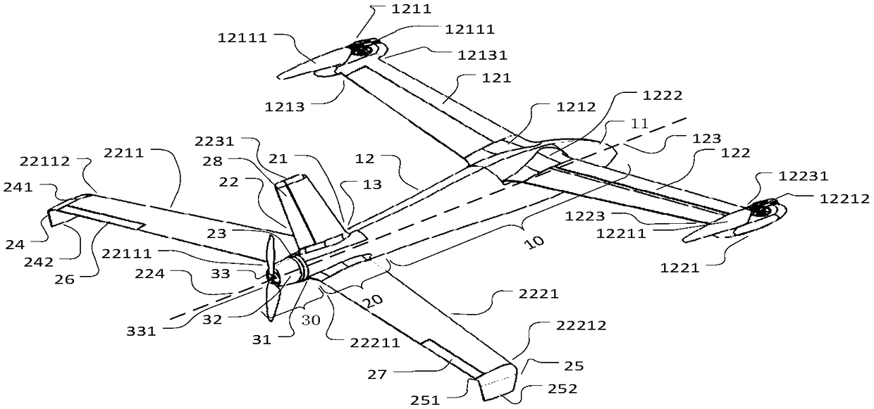
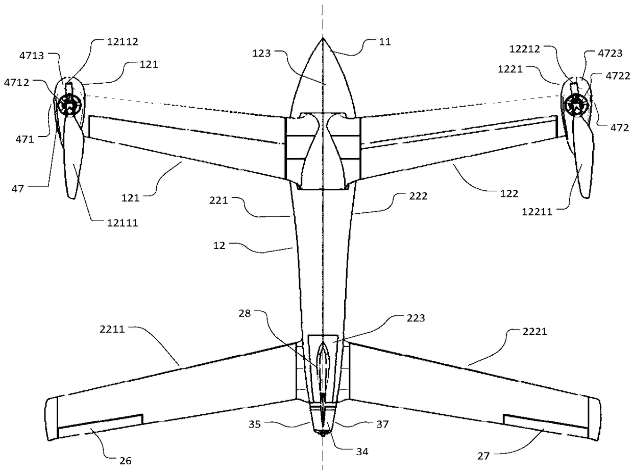
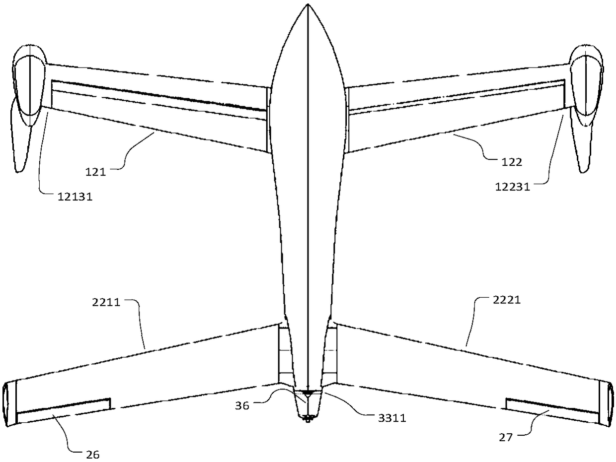
[0025] The invention discloses a rotor structure applied to an unmanned aerial vehicle. The first rotating blade and the first counterweight are respectively fixedly connected to the first rotor shaft, and the first rotating blade and the first counterweight are relative to the first The rotor shafts are distributed symmetrically; the first rotor shaft is perpendicular to the rotation plane of the first rotor blade; the second rotor blade and the second counterweight are fixedly connected to the second rotor shaft respectively, and the second rotor blade and the first The two counterweights are distributed symmetrically with respect to the second rotor axis; the second rotor axis is perpendicular to the rotation plane of the second rotary blade. At the same time, the tail spin seat is fixedly arranged on both sides of the second tail side and / or the fourth tail side of the drone, and the drive fixing seat is arranged on the tail spin seat and / or the third body; The first conne...


PUM


Abstract

The invention discloses a rotor wing structure applied to an unmanned aerial vehicle, belonging to the technical field of unmanned aerial vehicles. The rotor wing structure comprises a first rotor wing, and a first rotating blade of the first rotor wing is fixedly connected with a first rotor wing shaft of a steering engine; a first weight balancing block is fixedly connected with the first rotorwing shaft, and a first rotating blade and the first weight balancing block are symmetrically arranged relative to the first rotor wing shaft; a second rotating blade of a second rotor wing is fixedlyconnected with a second rotor wing shaft of the steering engine; the second weight balancing block is fixedly connected with the second rotor wing shaft, and the second rotating blade and the secondweight balancing block are symmetrically arranged relative to the second rotor wing shaft. A first driving motor comprises a first driving shaft and a driving and fixing seat; tail spin seats are fixedly arranged on two sides of a second and / or fourth tail side surfaces, and the driving and fixing seat is arranged on the tail spin seat and / or a third body; a third steering engine comprises a thirdrotor wing shaft and a third fixing seat; a linkage part comprises a first joining end, a second joining end and a tail rotor wing. The rotor wing structure has the technical effects that pushing force and pulling force are supplied for the unmanned aerial vehicle to take off and land as well as to fly in the whole journey, the rotor wing structure is simple, and the maintenance is convenient andfast.

Description

technical field [0001] The invention belongs to the technical field of unmanned aerial vehicles, in particular to a rotor structure applied to unmanned aerial vehicles. Background technique [0002] Unmanned UAV, referred to as "UAV", is an unmanned UAV controlled by radio remote control equipment and its own program control device. The rotor is the main lift component of the UAV. During the flight of the UAV, the rotor plays a role in generating lift. [0003] Currently, rotors are made up of multiple (more than 2) blades, and as the blades in the rotor rotate, the blades will interact with the surrounding air, creating a pulling force along the rotor axis that will give the aircraft an upward movement of lift. By adjusting the rotation speed of the blades, the magnitude of the lift is controlled, so that the aircraft can take off and land. At the same time, before the UAV leaves the factory, the rotor is often installed on the top of the UAV. When the blades in the roto...

Claims


Application Information

Patent Timeline
29 Jun 2018
Publication
CN108216611A
IPC
B64C27/22; B64C27/32; B64C27/52; B64C27/467
CPC
B64C27/22; B64C27/32; B64C27/467; B64C27/52
Inventors
赵国成; 漆鹏程