Self-controlled control textile winding mechanism

A winding mechanism and textile technology, applied in the direction of conveying filamentous materials, thin material processing, transportation and packaging, etc., can solve the problems of inconvenient use, low work efficiency, waste of man-hours, etc., to improve work efficiency and improve efficiency. , easy to use effect

Inactive Publication Date: 2018-07-17
QUZHOU YANHANG MACHINERY TECH CO LTD
View PDF0 Cites 0 Cited by
  • Summary
  • Abstract
  • Description
  • Claims
  • Application Information

AI Technical Summary

Problems solved by technology

In the existing winding device, there is often only a single winding, and the work efficiency is low. After one winding, the winding barrel needs to be replaced, and then the winding is continu

Method used


Image

  • Self-controlled control textile winding mechanism
  • Self-controlled control textile winding mechanism
  • Self-controlled control textile winding mechanism

Examples


Embodiment Construction

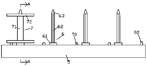
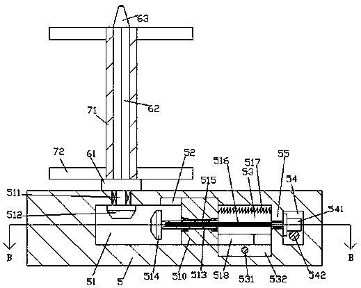
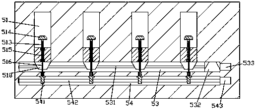
[0022] Such as Figure 1-Figure 6 As shown, a self-selective control textile winding mechanism of the present invention includes a base 5 and winding mechanisms 6 equidistantly distributed on the top end surface of the base 5, and each of the bases 5 below the winding mechanism 6 There is a drive cavity 51 extending to the front side inside. The rear side of the drive cavity 51 is communicated with a first cavity 53 extending left and right. The base 5 on the front side of the first cavity 53 is provided with a The second cavity 54, a partition 55 is arranged between the first cavity 53 and the second cavity 54, and the inner top wall on the front side of each first cavity 53 is provided with a guide groove 52 Each of the sliding guide grooves 52 is provided with a sliding block 510 extending downward, and the bottom extension of the sliding block 510 extends into the driving cavity 51 and slidably fits with the inner bottom wall of the driving cavity 51 connected, each of th...


PUM


Abstract

The invention discloses a self-controlled textile winding mechanism. The self-controlled textile winding mechanism comprises a base and winding mechanism bodies distributed on the top end face of thebase at equal intervals, wherein a driving cavity extending to the front side is arranged in the position, below each winding mechanism body, of the base; a first cavity arranged in a left-and-right extension manner is arranged in the rear side of each driving cavity in a communication manner; a second cavity is arranged in the position, on the front side of each cavity, of the base; a separationplate is arranged between each first cavity and the corresponding second cavity, the inner top wall of the front side of each first cavity is provided with a guide sliding groove, a sliding block arranged in a downward extension manner is arranged in each guide sliding groove, the bottom extension sections of the sliding blocks stretch into the driving cavities and are connected with the inner bottom walls of the driving cavities in a sliding fit manner, the interior of each sliding block is connected with a first rotating shaft in a rotating fit manner, and the first rotating shafts are arranged in a manner of extending to the rear sides. The self-controlled textile winding mechanism is simple in structure, can realize installation of multiple winding reels, there is no need to replace the winding reel after the winding reel is wound, time and labor are saved, and the efficiency is improved. In addition, no additional driving device is required, the manufacturing cost is reduced, andthe purchasing cost of an enterprise is reduced.

Description

technical field [0001] The invention relates to the technical field of textile processing machinery, in particular to a self-selectively controlled textile winding mechanism. Background technique [0002] In the textile industry, a neat and uncluttered coil is the prerequisite for weaving good products. Therefore, since ancient times, people have arranged the threads before weaving, and wound them into a neat ball for storage and transportation. Or the textile work in the next process, it is one of the very important textile machinery and equipment in modern textile enterprises. In the existing winding device, there is often only a single winding, and the work efficiency is low. After one winding, the winding barrel needs to be replaced, and then the winding is continued, which is a waste of man-hours and low in efficiency. In addition, if more The winding device requires an additional driving device, which increases the cost and is very inconvenient to use. Contents of t...

Claims


Application Information

Patent Timeline
IPC IPC(8): B65H54/20B65H54/74
CPCB65H54/20B65H54/74B65H2403/43B65H2403/46B65H2403/52B65H2403/55B65H2403/90B65H2701/35
Inventor 何海燕
Owner QUZHOU YANHANG MACHINERY TECH CO LTD
Why Eureka
Try Eureka