Thermostatic cartridge for controlling hot and cold fluids to be mixed

A technology of constant temperature spool and thermal fluid, applied in temperature control, engine cooling, non-electric variable control, etc., can solve the problem of limited outer diameter and achieve the effect of increasing the outer diameter of the slide valve

Active Publication Date: 2018-08-03
VERNET SA
View PDF10 Cites 2 Cited by
  • Summary
  • Abstract
  • Description
  • Claims
  • Application Information

AI Technical Summary

Problems solved by technology

This solution makes it possible to cause a large flow rate through the base to the slide valve, but the outer diameter of the

Method used


Image

  • Thermostatic cartridge for controlling hot and cold fluids to be mixed
  • Thermostatic cartridge for controlling hot and cold fluids to be mixed
  • Thermostatic cartridge for controlling hot and cold fluids to be mixed

Examples


Embodiment Construction

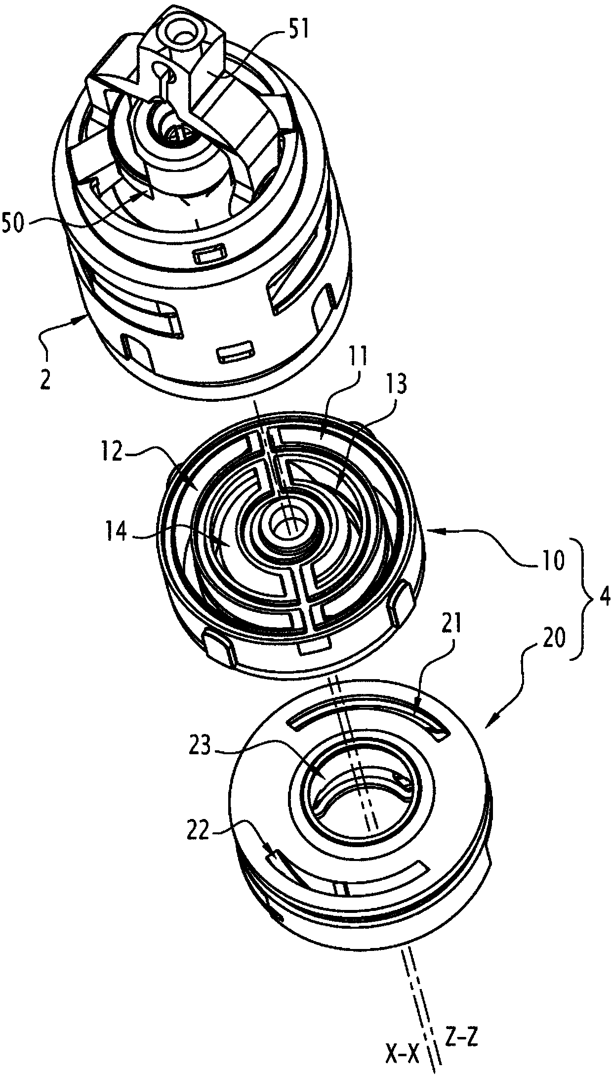
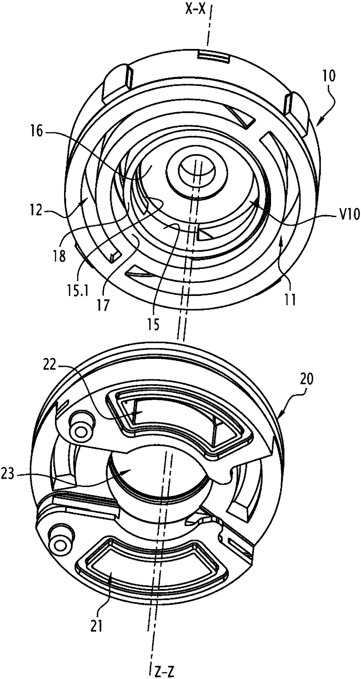
[0017] Figure 1 to Figure 7 A thermostatic spool 1 arranged along the main axis X-X is shown. This cartridge is suitable for equipping taps (not shown in the figures) for mixing hot and cold water, or more generally for equipping sanitary facilities.

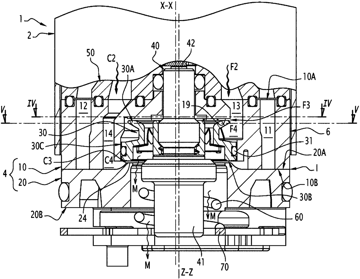
[0018] For convenience, the remainder of the description is oriented relative to the axis X-X, considering that the terms "upper" and "top" etc. image 3 , 6 and 7 are the axial direction of the upper part, while the terms "lower" and "bottom" etc. correspond to the axial direction in the opposite sense.

[0019] The thermostatic valve core 1 comprises an upper housing 2 and a lower base 4 which are fixedly assembled to each other in the assembled state of the valve core.

[0020] The base 4 has a generally cylindrical external shape, with a cylindrical peripheral surface 6 centered on the axis X-X. The axis X-X is thus defined by the periphery of the base and can therefore be described as the base axis. In the example cons...


PUM


Abstract

This cartridge (1) comprises a base (4), that defines a base axis (X-X) on which an outer peripheral face (6) of the base is centred, and that includes first (10) and second (20) base portions that follow one another along the base axis, the first base portion delimiting a first inlet opening (13) for a first of the cold and hot fluids to be mixed, and a second inlet opening (14) for the second fluid, while the second base portion delimits an outlet opening for a mixture of the cold and hot fluids. The cartridge also comprises a thermostatic element(40), as well as a control spool (30) for controlling the temperature of the mixture, which defines a spool axis (Z-Z) parallel to the base axis and is linked to the body (41) of the thermostatic element so as to be moved along the spool axis insuch a way as to vary, in an inverse manner, the respective flow sections of a first passage (F3) for the first fluid and a second passage (C3) for the second fluid, said passages being respectivelysupplied by the first inlet opening and the second inlet opening, extending around the spool axis while being centred on said spool axis, and being delimited axially between the spool and the first and second base portions. In order to maximise the flow sections of the fluids through the base, the spool axis is offset relative to the base axis.

Description

【Technical field】 [0001] The invention relates to a thermostatic valve cartridge for controlling hot and cold fluids to be mixed, especially hot and cold water in sanitary facilities. 【Background technique】 [0002] Such cartridges include a base in which the hot and cold fluids circulate until they are mixed before leaving the base. This base is designed to be installed in a tap or more generally in a plumbing fixture that is supplied with hot and cold fluid and delivers a mixture of these fluids: the base therefore has limited The external geometry, since it must adapt to the internal space of the body of this sanitary fixture dedicated to the installation of the base. Typically, the base has a cylindrical outer geometry with a circular base, the diameter of which is for example between 35mm and 40mm. Considering that the central axis of the susceptor, defined by its external geometry, runs vertically, the present invention examines common configurations in which the flu...

Claims


Application Information

Patent Timeline
IPC IPC(8): G05D23/13F16K11/044
CPCF16K11/044F16K31/002G05D23/1353F01P7/16
Inventor 弗雷德里克·耶格尔
Owner VERNET SA
Why Eureka
Try Eureka