Iron tower steel pile underground communication machine room

An underground communication and computer room technology, applied in the field of communication, can solve problems such as equipment and battery theft cases, affecting operation, excessive power consumption, etc., and achieve the effect of improving the safety range of pedestrians, preventing equipment from being stolen, and lowering the construction threshold

Active Publication Date: 2018-08-14
CHANGCHUN HUICHUNYUAN COMM CO LTD
View PDF8 Cites 2 Cited by
  • Summary
  • Abstract
  • Description
  • Claims
  • Application Information

AI Technical Summary

Problems solved by technology

In addition, the operation of the equipment in the communication room in the prior art will generate too much heat. If the temperature is too high, the equipment will be damaged and affect the operation. Ventilation and heat reduction mainly rely on air conditioning equipment. Excessive reliance on air conditioning will inevitably lead to excessive consumption of electricity. 55% of the electricity consumption of the country comes from air conditioners, and the total electricity consumption of base station air conditioners across the country will be a very large number.
Ordinary base station communication rooms are mostly made of color steel plates, the anti-theft effect is not good, equipment and batteries are stolen frequently, and the wind resistance of the iron tower communication room in the prior art is not good, so a new type of computer room to solve the above problems

Method used


Image

  • Iron tower steel pile underground communication machine room
  • Iron tower steel pile underground communication machine room
  • Iron tower steel pile underground communication machine room

Examples


Embodiment Construction

[0027] The following examples are used to illustrate the present invention, but are not intended to limit the scope of the present invention.

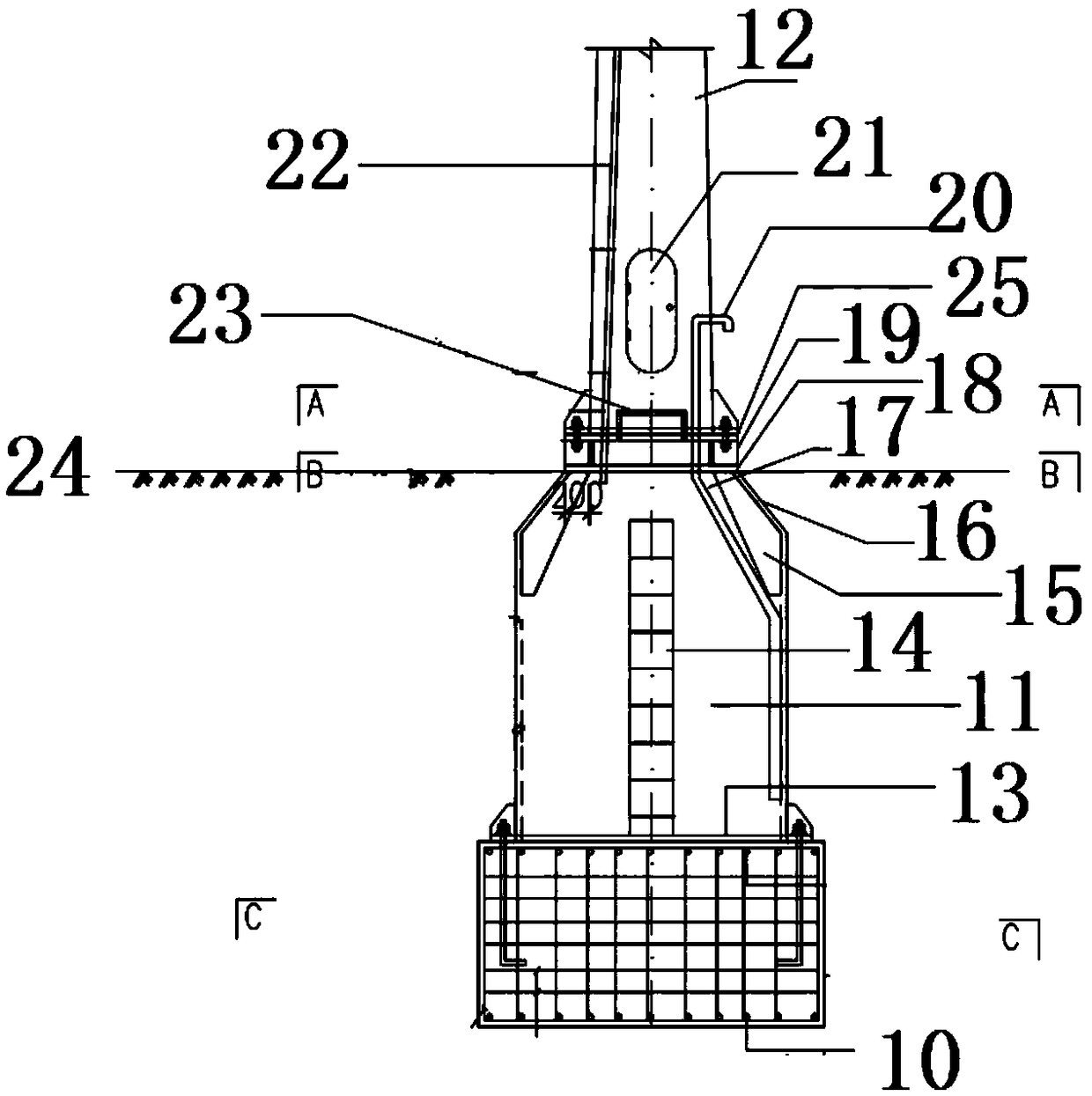
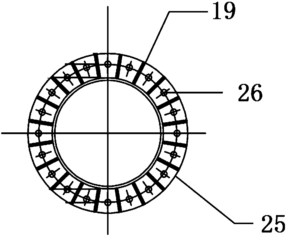
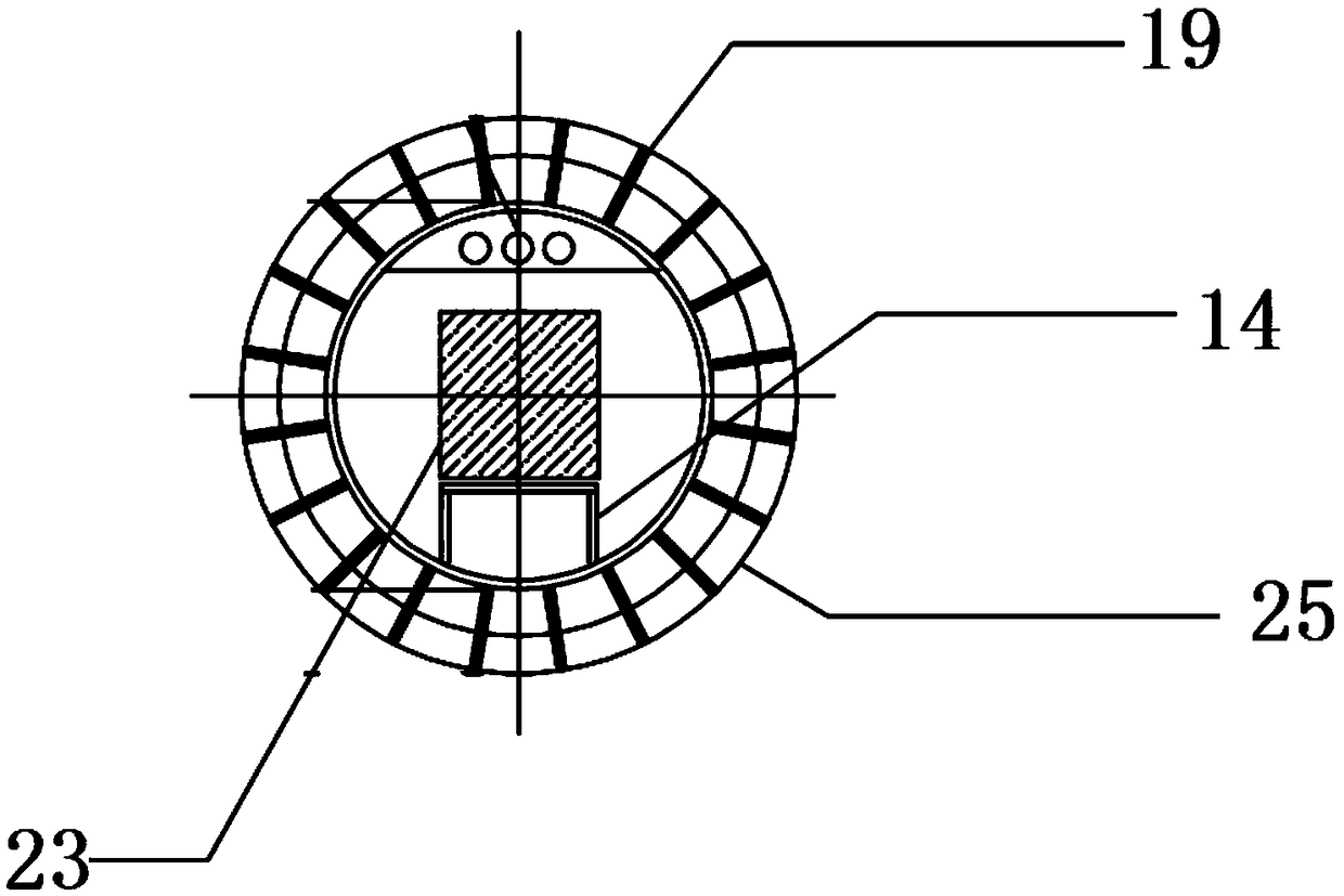
[0028] Such as Figure 1 to Figure 4 As shown, the iron tower and steel pile underground communication machine room of the present invention includes a foundation part 10, a machine room part 11 and a beautification tower part 12. The upper machine room flange is connected; the upper part of the bottom plate is provided with a hollow equipment cabin, and the top of the equipment cabin is connected with the conical pipe 16; the inside of the equipment cabin is provided with an internal bridge, and equipment is installed on the internal bridge. The equipment is suspended. The inside of the equipment cabin is provided with an air inlet duct 20, and the outside is provided with an air inlet; the upper part of the equipment cabin is provided with an air outlet; Below the ground level 24; the top of the machine room part is connected to the...


PUM


Abstract

The invention discloses an iron tower steel pile underground communication machine room which comprises a foundation part, a machine room part and a beautifying tower part. A bottom plate is arrangedat the bottom of the machine room part, and the foundation part is connected with a machine room flange on the bottom plate through prefabricated bolts. A hollow equipment bin is arranged above the bottom plate, and the top of the equipment bin is connected with a tapered pipe. An internal bridge frame is arranged in the equipment bin, and equipment is mounted on the internal bridge frame and adopts a suspension mode. An air inlet pipeline is arranged in the equipment bin, and an air inlet is formed outside the equipment bin. An air discharging opening is formed in the upper portion of the equipment bin, and a ventilating pipeline, an optical cable pipeline and a power supply pipeline are arranged at the top of the machine room part. The foundation part and the machine room part are both buried in the position below the ground level. The top of the machine room part is connected with the beautifying tower part, and the ventilating pipeline penetrates through the interior of the beautifying tower part. A rain-proof cap is arranged on the upper portion of the beautifying tower part, and a manhole with a door is formed in the side wall of the beautifying tower part. An anti-theft irondoor is arranged at the manhole with the door and adopts a special anti-theft door lock.

Description

technical field [0001] The invention relates to the technical field of communication, in particular to an underground communication machine room with steel towers and steel piles. Background technique [0002] The communication room is an indispensable key link in the communication construction. It is connected to the communication data center on one side and one or several RRU.BBU communication base stations on the other side. In communication, it plays a key role in the conversion and emission of signals. [0003] Taking the communication room of the iron tower as an example, the general communication room is in the form of a building, or a board room, or an integrated warehouse. This kind of common communication room occupies more resources and is difficult to construct. Take an ordinary steel tower board room base station as an example; it generally covers an area of ​​60-150 square meters, which is large and difficult to coordinate; it has a great impact on the surrou...

Claims


Application Information

Patent Timeline
Patent Type & Authority Applications(China)
IPC IPC(8): E04H5/04E02D27/42F24F7/00F24F7/04
CPCE02D27/42E04H5/04F24F7/00F24F7/04F24F2007/005
Inventor 王永光王樱默
Owner CHANGCHUN HUICHUNYUAN COMM CO LTD
Why Eureka
Try Eureka