Fingerprint attendance machine with sliding surface cover

A technology of attendance machine and sliding surface, which is applied in the direction of registration/instruction, computer parts, recording/indication event time, etc., can solve the problems that affect the speed of attendance completion, damage to parts, troubles, etc., and achieve a stable installation method. The effect of increasing the service life

Inactive Publication Date: 2018-09-04
丁可
View PDF0 Cites 3 Cited by
  • Summary
  • Abstract
  • Description
  • Claims
  • Application Information

AI Technical Summary

Problems solved by technology

[0003] Common fingerprint time attendance machines on the market do not have a protective casing, and the parts of the time attendance machine are exposed. On the one hand, it is easy to accumulate dust, resulting in a decrease in the accuracy of the fingerprint time attendance machine. The service life is shortened; the common fingerprint time attendance machine is installed by hanging on the expansion screw. As the use time increases, the expansion screw will shake, so this installation method is very unstable; If there is some water, especially in hot summer, there will be a lot of sweat on your hands. At this time, you need to use a paper towel to wipe off the water on your fingers, so as not to affect the efficiency of fingerprint recognition, but this operation is very troublesome; common fingerprint attendance The machine has only one fingerprint identification module. During the peak hours of commuting, people need to wait in line to check in, which affects the speed of people completing attendance. Therefore, we propose a fingerprint time attendance machine with a sliding cover.

Method used


Image

  • Fingerprint attendance machine with sliding surface cover
  • Fingerprint attendance machine with sliding surface cover
  • Fingerprint attendance machine with sliding surface cover

Examples


Embodiment Construction

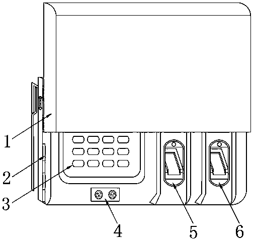
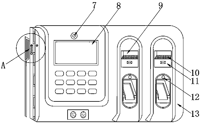
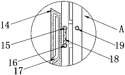
[0024] see Figure 1-5 , in an embodiment of the present invention, a fingerprint attendance machine with a sliding cover includes a housing 13, the front surface of the housing 13 is embedded with a display screen 8, and the front surface of the housing 13 is embedded and installed close to the top of the display screen 8 There is a camera 7, the front surface of the housing 13 is embedded with the button 3 of the control body near the bottom of the display screen 8, the front surface of the housing 13 is provided with a loudspeaker 4 near the bottom of the button 3, and the two sides of the housing 13 Both are provided with a slide rail 2, the upper surface of the slide rail 2 is slidably connected with a slide cover 1 slightly larger than the main body, and the front surface of the housing 13 close to the side of the display screen 8 is horizontally installed with a first fingerprint reader 5 and a second fingerprint reader in turn. Fingerprint reader 6, the front surface o...


PUM


Abstract

The invention discloses a fingerprint attendance machine with a sliding surface cover. The fingerprint attendance machine with the sliding surface cover comprises a shell; a display screen is embeddedon the front surface of the shell; a camera is embedded in the front surface of the shell and near the above position of the display screen; a key of a control body is embedded on the front surface of the shell and near the lower position of the display screen; and a loudspeaker is arranged on the front surface of the shell and near the lower part of the key. Through a sliding cover and a slidingrail, the sliding cover slides down when the fingerprint attendance machine does not need to be used and the sliding cover just can cover the body, so that parts of the body are not bare outside, theservice life of the body is prolonged, dust is prevented from falling on a fingerprint identifier, and the accuracy degree of attendance is influenced; when the body needs to be used, the sliding cover slides upwards, a limiting rod rotates, a limiting ring at the rotating end of the limiting rod is in sleeving connection with a limiting column when the limiting rod rotates to the horizontal position, and the limiting ring at the rotating end of the limiting rod is in sleeving connection with the limiting column, so that the fact that the sliding cover slides down under the gravity action isavoided.

Description

technical field [0001] The invention relates to an attendance check machine, in particular to a fingerprint attendance check machine with a sliding cover. Background technique [0002] There are two types of attendance machines: the first type is simple printing. When clocking in, the original record data is directly printed on the card through the attendance machine. The recorded time on the card is the original attendance information, and there is no need to do any prior The training can be used immediately; the second type is the storage type. When clocking in, the original recorded data is directly stored in the attendance machine, and then collected and summarized by the computer, and then processed by software, and finally the required attendance information is formed or queried or printed. Its attendance information is flexible and rich, and the first-time users need to do some training in advance to gradually master all its functions. The common storage type time att...

Claims


Application Information

Patent Timeline
Patent Type & Authority Applications(China)
IPC IPC(8): G07C1/10G06K9/00A61L9/20
CPCA61L9/20G07C1/10G06V40/13
Inventor 田梦颖丁可倪宝铜郝曼靖李根付杰张彩霞
Owner 丁可
Why Eureka
Try Eureka