Al technical title is built by PatSnap Al team. It summarizes the technical point description of the patent document.
A water dispenser and backing plate technology, which is applied in the field of backing plates for water dispensers, can solve problems such as inconvenient fixing of water dispensers, unreasonable use of water droplets, single function of backing plates, etc., and achieves good drying effect and increased stability , Improve the effect of installation stability
Inactive Publication Date: 2018-09-11
王伟
View PDF5 Cites 3 Cited by
Summary
Abstract
Description
Claims
Application Information
AI Technical Summary
This helps you quickly interpret patents by identifying the three key elements:
Problems solved by technology
Method used
Benefits of technology
Problems solved by technology
[0003] In the prior art, the backing plate used for the existing water dispenser is not equipped with a fixing device, and the backing plate used for the water dispenser simply provides a placement function, which cannot facilitate the fixing of the water dispenser. There is no energy-saving and de-drying function. When the water dispenser is discharging water, it is inevitable that there will be residual water droplets covering the backing plate, which will affect the cleaning around the backing plate. At the same time, the remaining water droplets cannot be used reasonably. The function of the backing plate is single, so now there is an urgent need for a backing plate for water dispensers to solve the above-mentioned problems
Method used
Image
Click on the blue label to locate the original text in one second.
Reading with bidirectional positioning of images and text.
Examples
Embodiment Construction
[0019] In order to make the technical means, creative features, goals and effects achieved by the present invention easy to understand, the present invention will be further described below in conjunction with specific embodiments.
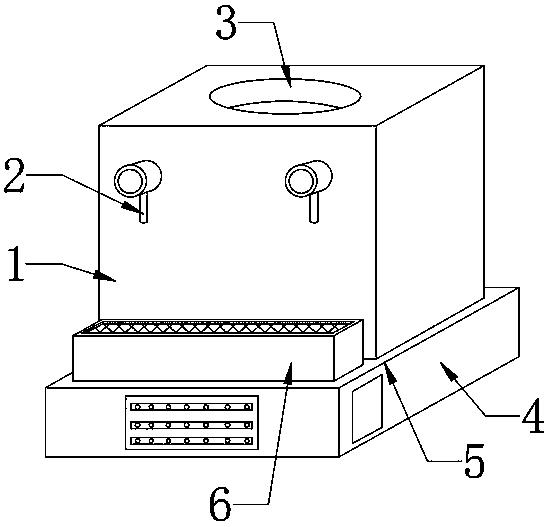
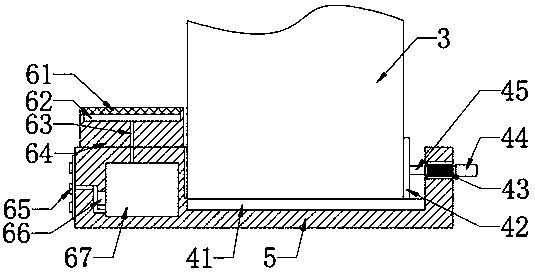
[0020] see Figure 1-Figure 2 , the present invention provides a technical solution: a backing plate for a water dispenser, including a water dispenser 1, a faucet 2, a water inlet 3, a fixing mechanism 4, a main body of the backing plate 5, and an energy-saving dedrying mechanism 6. The water dispenser 1 is assembled on the backing plate On the rear side of the upper end surface of the plate main body 5, the faucets 2 are symmetrically installed on the left and right sides of the front surface of the water dispenser 1, the water inlet 3 is set on the upper inner side of the water dispenser 1, the fixing mechanism 4 is arranged inside the backing plate main body 5, and the energy-saving dedrying mechanism 6 is arranged on the front side of the upp...
PUM
Abstract
The invention provides a base plate for a water dispenser. The base plate comprises a base plate main body, a damping plate, an extrusion plate, a spring, an anti-sliding sleeve, a connecting rod, a separation net, a water collection tank, a connecting pipe, a nozzle, a miniature pump and a water collection box, wherein the damping plate is mounted on the rear side in the base plate main body, theextrusion plate is mounted on the front end surface of the connecting rod, the spring is fixed to the annular side surface of the connecting rod, the connecting rod is mounted on the rear side in thebase plate body, and the rear side of an annular side surface is packaged with the connecting rod. According to the design, the water dispenser can be conveniently and fixedly placed, so that the stabilization effect of the base plate is improved; the separation net is mounted on the upper side of the water collection tank, the water collection tank is formed in the upper side in a fixed block, the connecting pipe is mounted on the lower side of the water collection tank, the water collection box is mounted on the front side in the base plate main body, the nozzle is mounted on the front sidesurface of the base plate main body, and the miniature pump is mounted on the front side of the water collection box, so that the problems that a base plate of a primary water dispenser does not haveenergy-saving and moistening functions are solved; and the base plate is reasonable in structure, strong in stability and high in reliability and has a very good moistening effect.
Description
technical field [0001] The invention relates to a backing plate for a water dispenser, which belongs to the field of daily necessities equipment. Background technique [0002] A water dispenser is a device that heats up or cools down bottled pure water or mineral water and makes it convenient for people to drink. Put bottled water on the top of the machine, and use the water dispenser with the bottled water. In summary, it can be divided into three types: warm, ice heat, and ice heat. The ice heat machine is divided into semiconductor refrigeration water dispenser and compressor refrigeration water dispenser , The water dispenser usually needs to use a backing plate when it is fixedly placed. Installing a reliable backing plate can effectively protect the water dispenser from damage. [0003] In the prior art, the backing plate used for the existing water dispenser is not equipped with a fixing device, and the backing plate used for the water dispenser simply provides a pla...
Claims
Application Information
Patent Timeline
Application Date:The date an application was filed.
Publication Date:The date a patent or application was officially published.
First Publication Date:The earliest publication date of a patent with the same application number.
Issue Date:Publication date of the patent grant document.
PCT Entry Date:The Entry date of PCT National Phase.
Estimated Expiry Date:The statutory expiry date of a patent right according to the Patent Law, and it is the longest term of protection that the patent right can achieve without the termination of the patent right due to other reasons(Term extension factor has been taken into account ).
Invalid Date:Actual expiry date is based on effective date or publication date of legal transaction data of invalid patent.