Design method of a three-power combination engine with co-existing super-combustion and sub-combustion combustion chambers

A sub-combustion combustion chamber and engine technology, applied in the field of three-power combination engine design, can solve the problems of long-distance engineering practice and low maturity, and achieve the effects of wide working speed range, reduced complexity, and moderate technical difficulty

Active Publication Date: 2019-10-18
XIAMEN UNIV
View PDF7 Cites 0 Cited by
  • Summary
  • Abstract
  • Description
  • Claims
  • Application Information

AI Technical Summary

Problems solved by technology

However, the current dual-mode scramjet technology is relatively low-maturity and far from engineering practice.

Method used


Image

  • Design method of a three-power combination engine with co-existing super-combustion and sub-combustion combustion chambers
  • Design method of a three-power combination engine with co-existing super-combustion and sub-combustion combustion chambers

Examples


Embodiment Construction

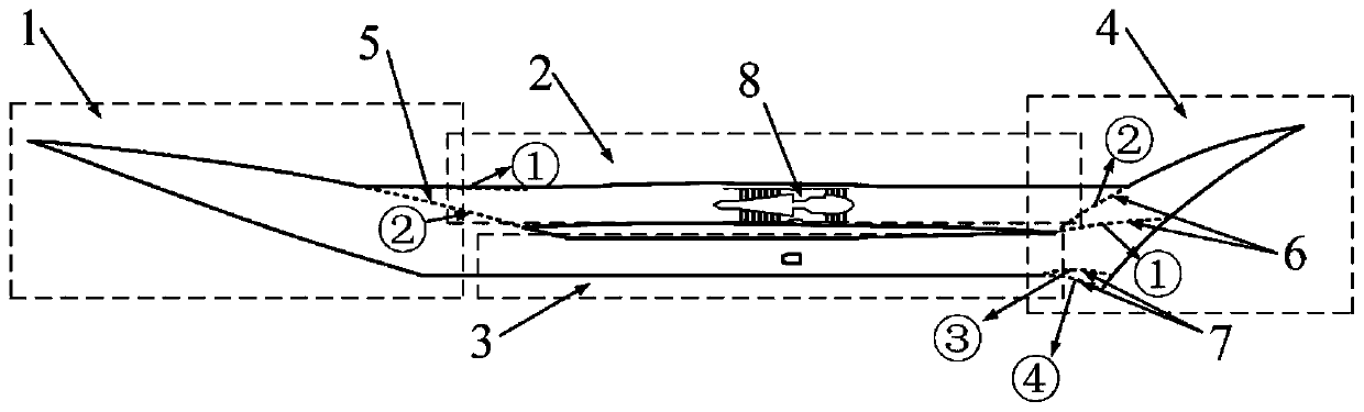
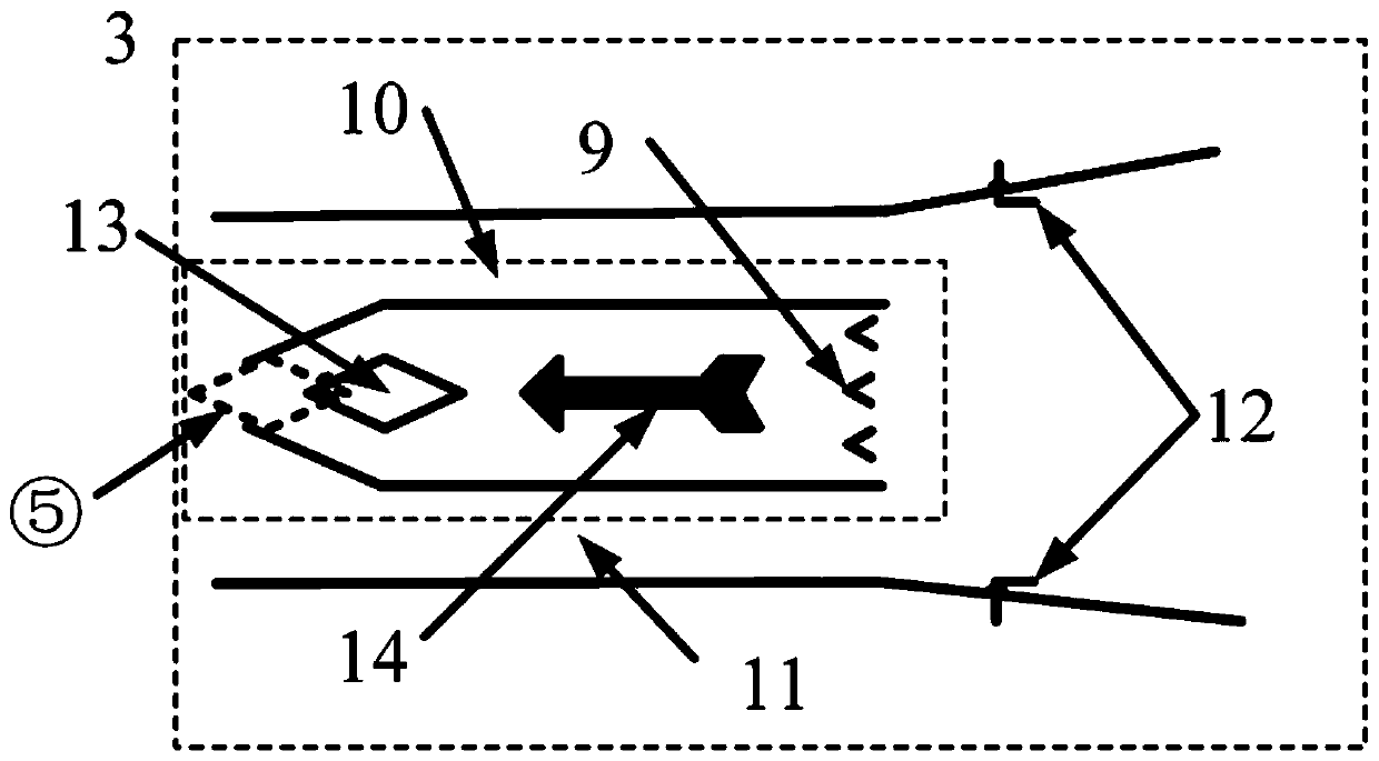
[0017] Such as figure 1 and figure 2 As shown, the three-power combination engine in which the super-combustion and sub-combustion combustion chambers coexist includes a three-dimensional internal rotation inlet 1, a turbine channel 2, a ram rocket combination channel 3 and a tail nozzle 4. When the flight Mach number is 0-2, the turbine engine 8 is ignited and working. At this time, the splitter plate 5 in the three-dimensional inner contraction inlet 1 is at the top, that is, the state ①, and the splitter plate 6 in the tail nozzle 4 is in the middle, that is, the state ① , so that the airflow can flow through both the turbine channel 2 and the ram rocket channel 3 . However, the ram rocket channel 3 is not ignited and is in a state of leakage; when the flight Mach number is 2 to 3, the rocket engine 14 and the sub-combustion combustion chamber 9 are ignited to work, and the splitter plate 5 located in the air inlet 1 rotates downward at this time, In state ②, the diverte...


PUM


Abstract

The invention discloses a design method of a three-power combined engine with coexisting of supersonic combustion combustor and a subsonic combustion combustor, and relates to a combined engine. According to the flight mission, the overall performance requirement is formulated, a basic flow field is designed based on the overall performance requirement, and then a three-dimensional internal turning air passage is obtained by streamline tracing. In a three-dimensional internal turning air passage outlet, according to the overall performance of the engine, the inlet and outlet parameters of thesupersonic combustion combustor are obtained, and the supersonic combustion combustor is designed. In front of a supersonic combustion combustor inlet, an ejection rocket passage of corresponding sizes are arranged based on a thrust requirement of the Ma2-5 engine, and a central cone, a rocket engine and the subsonic combustion combustor are included. According to the flow requirement of the engine in a Ma0-2 stage, the area of a turbine passage inlet is calculated by using the flow formula shown in the specification, an opening is formed in the wall surface of the three-dimensional internal turning air passage, and the turbine passage is arranged. A common tail spraying pipe with an adjustable geometric area is arranged at a supersonic combustion combustor outlet and the turbine passage outlet, and a spreader plate is designed according to the different working conditions of the tail spraying pipe.

Description

technical field [0001] The invention relates to a combination engine, in particular to a design method of a three-power combination engine in which super-combustion and sub-combustion combustion chambers coexist. Background technique [0002] Hypersonic flight is known as the third "revolution" in aviation history after propeller propulsion flight and jet propulsion flight, and it is the commanding height of aviation and aerospace science and technology in the 21st century ([1] Wang Xuhao, Wang Wenfa, Wang Zhaolei. The characteristics of hypersonic vehicles and its impact on future operations[J]. Flying Missiles, 2011(5):26-28.). At present, the frontiers of academic research on aerospace vehicles are shifting from the development of scramjet engines to the development of combined power systems capable of horizontal take-off and autonomous acceleration to hypersonic speeds ([2] Liu Daxiang, Chen Guang. Aeroengines in the 21st Century ( Next) [J]. Aviation Knowledge, 2004(6)...

Claims


Application Information

Patent Timeline
Patent Type & Authority Patents(China)
IPC IPC(8): F02K7/16F02K7/18F02K7/14
Inventor 朱剑锋施崇广尤延铖
Owner XIAMEN UNIV
Why Eureka
Try Eureka