Multi-cutter farmland plow and operation method

A cutting tool and arable land technology, which is applied to plows, agricultural machinery and implements, applications, etc., can solve the problems of adjusting the angle of the cutting tool and the lack of data of the cutting tool when plowing cannot be done.

Active Publication Date: 2018-11-13
GUIZHOU INST OF TECH
View PDF6 Cites 3 Cited by
  • Summary
  • Abstract
  • Description
  • Claims
  • Application Information

AI Technical Summary

Problems solved by technology

[0005] The purpose of the present invention is to provide a multi-cutter plow and its operation method to solve the probl...

Method used


Image

  • Multi-cutter farmland plow and operation method
  • Multi-cutter farmland plow and operation method
  • Multi-cutter farmland plow and operation method

Examples


Embodiment 1

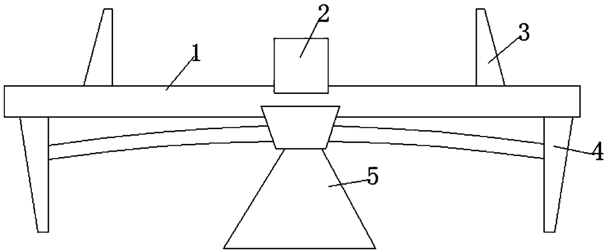
[0055] The multi-cutter plow of this embodiment 1 includes a frame 1, a first cutter assembly 4 is hinged at both ends of the lower side of the frame 1, and a second cutter assembly 4 is hinged at the middle of the lower side of the frame 1. Two cutter assemblies 5; a DSP controller 2 is fixed to the middle bolt on the upper side of the frame 1; the DSP controller 2 is used to control the inclination of the first cutter assembly 4 and the second cutter assembly 5 angle.

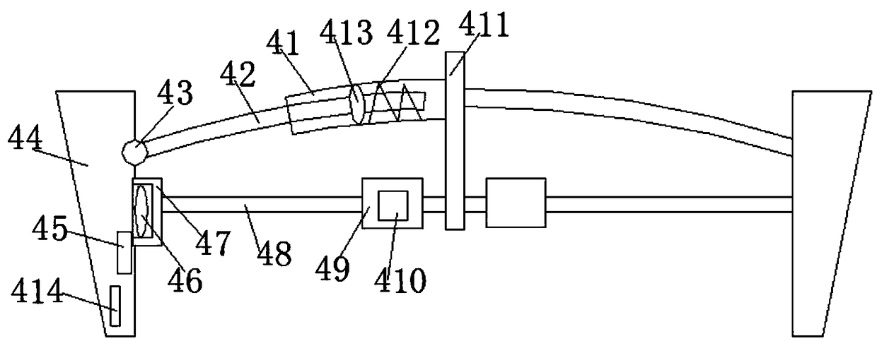
[0056] The first cutter assembly 4 includes a rectangular partition 411, a first telescopic tube 41 is fixed with bolts on the side wall of the top of the partition 411, and a circular ring is slid inside the first telescopic tube 41. arc-shaped first telescopic rod 42;

[0057] One end of the first telescopic rod 42 is hinged on the cutter 44 through the first hinge joint 43, and the other end is screwed with an elliptical retaining ring 413, and the retaining ring 413 slides on the first Inside the telesc...

Embodiment 2

[0078] Further, on the basis of embodiment 1:

[0079] The operation method of this embodiment 2 is used for the multi-cutter plow, comprising steps:

[0080] Step 1: Set the first target pressure value through the DSP controller 2, and set the first target angle to the first motor driver 410, and set the second target angle to the fourth motor driver 58;

[0081] Step 2: The multi-cutter plow starts to cultivate the land, the first pressure sensor 414 collects the pressure value and sends it to the DSP controller 2 for comparison, and the DSP controller 2 sends an adjustment command to the first pressure sensor 2 according to the comparison result. The motor driver 410, the fourth motor driver 58, the third motor driver 56 and the second motor driver 52;

[0082] Step 3: The first motor driver 410 , the fourth motor driver 58 , the third motor driver 56 and the second motor driver 52 respectively drive corresponding components for adjustment.

[0083] The multi-cutter plow ...


PUM


Abstract

The invention discloses a multi-cutter farmland plough. The plough comprises a frame, first cutter assemblies are hinged at both ends of the lower side of the frame, and a second cutter assembly is hinged to the middle of the lower side of the frame; a DSP controller is fixed to the middle of the upper side of the frame through a bolt; the DSP controller is used for controlling the tilt angles ofthe first cutter assemblies and the second cutter assembly; a first target pressure value is set by the DSP controller, a first target angle is set to a first motor driver, and a second target angle is set to a fourth motor driver; the multi-cutter farmland plough starts plowing, a first pressure sensor collects a pressure value and sends the pressure value to the DSP controller for comparison, and the DSP controller sends an adjustment command to the first motor driver, the fourth motor driver, the third motor driver and the second motor driver according to the comparison result; the first motor driver, the fourth motor driver, the third motor driver and the second motor driver respectively drive corresponding components to adjust to meet the plowing needs.

Description

technical field [0001] The invention relates to the technical field of agricultural machinery, in particular to a multi-cutter plow and an operation method. Background technique [0002] Cultivated land plows are widely used in the field of agriculture. In the process of plowing, due to the different soil properties of the land, the resistance encountered by the tool during the plowing process is also different; Adjust the cutting angle of the knife to achieve efficient plowing of the land. [0003] However, the traditional cultivated plow cannot adjust the angle of the cutter in real time according to the actual needs of the cultivated land; the traditional cultivated plow has a small number of knives, and it is not possible to set various soil cutting angles according to the needs of the cultivated land, and its soil plowing effect is poor . [0004] Therefore, it is necessary to provide a cultivated plow with a plurality of knives, and the inclination angle of the knive...

Claims


Application Information

Patent Timeline
IPC IPC(8): A01B15/02A01B15/14A01B15/18
CPCA01B15/02A01B15/14A01B15/18
Inventor 陈兴燕刘爱军孟春芬刘文拔
Owner GUIZHOU INST OF TECH
Why Eureka
Try Eureka