Automatic hooping machine

The technology of a hoop hoop machine and a hydraulic cylinder is applied in the field of hoop production and processing accessories, which can solve the problems of inconvenient adjustment, high use limitation, poor use reliability, etc., so as to reduce the use limitation, improve the supporting capacity, and facilitate fixing. Effect

Inactive Publication Date: 2018-12-21
HEBEI HONGYU COMM EQUIP
View PDF6 Cites 0 Cited by
  • Summary
  • Abstract
  • Description
  • Claims
  • Application Information

AI Technical Summary

Problems solved by technology

[0002] As we all know, the automatic hoop machine is an auxiliary device used in the production and processing of the hoop to extrude the steel plate to make it better for production and processing. It has been widely used in the field of hoop production and processing. ; Existing automatic hoop machine includes top plate, bottom plate, left side plate, right side plate, four groups of supports, the first hydraulic cylinder, the first telescopic rod, upper template and lower template, the top of left side plate and right side plate They are respectively installed on the left and right sides of the bottom of the top plate, the bottom ends of the left side plate and the right side plate are installed on the top of the bottom plate, and the tops of the four sets of brackets are respectively installed on the left front side, right front side, left rear side and right side of the bottom end of the bottom plate. On the rear side, the top of the first hydraulic cylinder is connected to the bottom of the top plate, the top of the first telescopic rod is connected to the output end of the bottom of the first hydraulic cylinder, the upper template is installed on the bottom of the first telescopic rod, the top of the bottom plate is provided with a fixing groove, and the lower template is installed Inside the fixed groove, the lower template is located directly below the upper template; when the existing automatic hoop machine is used, the steel plate is placed on the lower template, and the first hydraulic cylinder drives the upper template on the first telescopic rod to squeeze the steel plate to make it It can be formed; in the use of the existing automatic hoop machine, it is found that its overall function is relatively single, resulting in high limitations in its use; and its steel plate extrusion process, poor stability, resulting in its reliability Poor; and its overall height is fixed, it cannot be easily adjusted according to the height of the staff, which makes it more inconvenient to use

Method used


Image

  • Automatic hooping machine
  • Automatic hooping machine
  • Automatic hooping machine

Examples


Embodiment Construction

[0017] The specific implementation manners of the present invention will be further described in detail below in conjunction with the accompanying drawings and embodiments. The following examples are used to illustrate the present invention, but are not intended to limit the scope of the present invention.

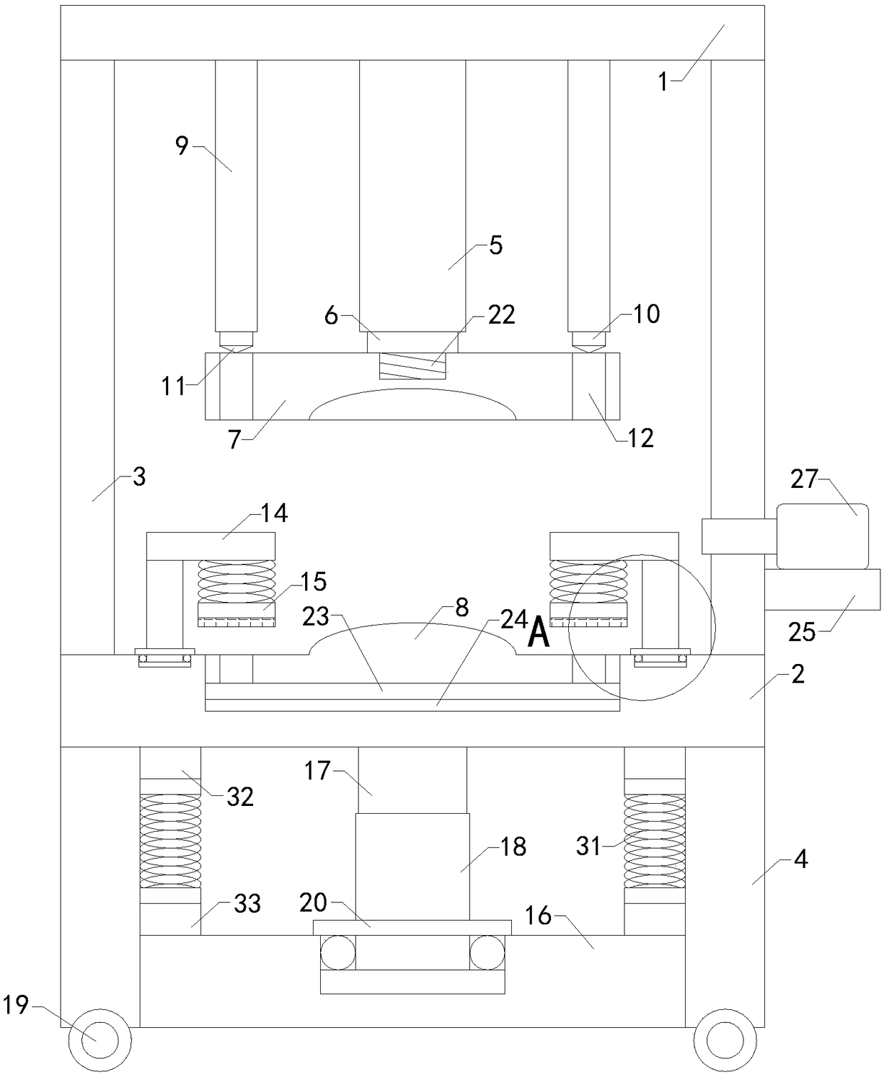
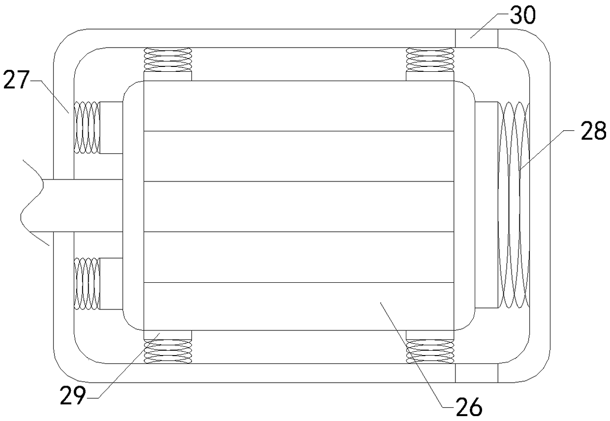
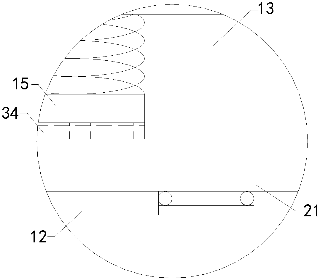
[0018] Such as Figure 1 to Figure 3 As shown, an automatic hoop machine of the present invention includes a top plate 1, a bottom plate 2, a left side plate 3, a right side plate, four sets of supports 4, a first hydraulic cylinder 5, a first telescopic rod 6, an upper template 7 and Lower formwork 8, the tops of the left and right panels are respectively installed on the left and right sides of the bottom of the top panel, the bottoms of the left and right panels are installed on the top of the bottom panel, and the tops of the four sets of brackets are respectively installed on the bottom panel The left front side, the right front side, the left rear side and the right...


PUM


Abstract

The invention relates to the technical field of hoop production auxiliary devices, in particular to an automatic hooping machine. The automatic hooping machine comprises a top plate, a base plate, a left side plate, a right side plate, four sets of brackets, a first hydraulic cylinder, a first extension rod, an upper template and a lower template; and a fixed groove is formed in the top end of thebase plate. The automatic hooping machine further comprises two sets of second hydraulic cylinders, two sets of second extension rods and two sets of drill bits; and through holes are formed in the left side and right side of the upper template and the left side and the right side of the lower template. The automatic hooping machine further comprises two sets of fixed columns, two sets of pressing rods, two sets of extrusion springs and two sets of pressing blocks. The automatic hooping machine further comprises a support plate, a third extension rod and a third hydraulic cylinder; universalwheels are rotationally arranged at the bottom ends of the four sets of brackets; a first placing tank is formed in the top end of the support plate; a first ball bearing and a first limiting piece are arranged in the first placing tank; a first stop piece is arranged at the top end of the first placing tank; and the bottom end of the third hydraulic cylinder penetrates through the first stop piece to insert in the first ball bearing and to connect with the first limiting piece.

Description

technical field [0001] The invention relates to the technical field of hoop production and processing attachments, in particular to an automatic hoop machine. Background technique [0002] As we all know, the automatic hoop machine is an auxiliary device used in the production and processing of the hoop to extrude the steel plate to make it better for production and processing. It has been widely used in the field of hoop production and processing. ; Existing automatic hoop machine includes top plate, bottom plate, left side plate, right side plate, four groups of supports, the first hydraulic cylinder, the first telescopic rod, upper template and lower template, the top of left side plate and right side plate They are respectively installed on the left and right sides of the bottom of the top plate, the bottom ends of the left side plate and the right side plate are installed on the top of the bottom plate, and the tops of the four sets of brackets are respectively installe...

Claims


Application Information

Patent Timeline
Patent Type & Authority Applications(China)
IPC IPC(8): B21D22/02B23P23/04
Inventor 熊怀忠
Owner HEBEI HONGYU COMM EQUIP
Why Eureka
Try Eureka