A coil pressing device

A compression device and coil technology, which is applied in coil manufacturing and other directions, can solve the problems of time-consuming and labor-intensive installation and inconvenient coil placement.

Active Publication Date: 2020-06-16
JIANGXI YAWEI ELECTRIC
View PDF5 Cites 0 Cited by
  • Summary
  • Abstract
  • Description
  • Claims
  • Application Information

AI Technical Summary

Problems solved by technology

The existence of the screw in this form undoubtedly brings inconvenience to the placement of the coil on the hydraulic machine. Of course, some equipment installs the coil first and then installs the screw. The installation of such a long screw is usually time-consuming and laborious.

Method used


Image

  • A coil pressing device
  • A coil pressing device
  • A coil pressing device

Examples


Embodiment Construction

[0019] In order to facilitate the understanding of the present invention, the present invention will be described more fully below with reference to the associated drawings. A preferred embodiment of the invention is shown in the drawings. However, the present invention can be embodied in many different forms and is not limited to the embodiments described herein. Rather, these embodiments are provided so that the disclosure of the present invention will be thorough and complete.

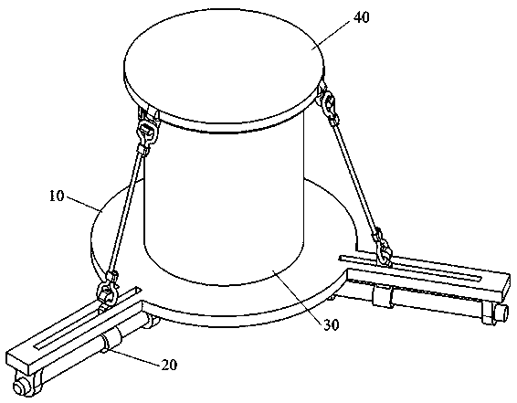
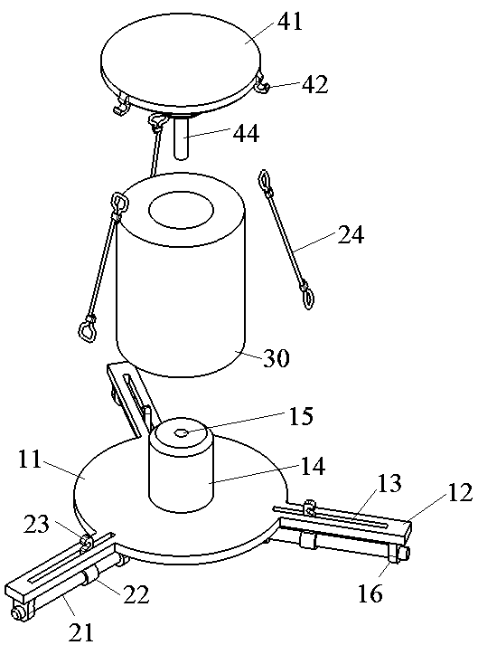
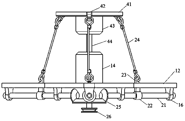
[0020] see Figure 1~Figure 4 The coil pressing device shown includes a supporting part 10, a transmission part 20 and a pressing part 40, the pressing part 40 is installed above the supporting part 10, and the coil 30 is placed between the pressing part 40 and the supporting part 10, and the transmission part 20 The pressing part 40 is pulled downward to realize the pressing effect on the coil 30 .

[0021] The supporting part 10 includes a base 11 , a beam 12 , a slide groove 13 , a lower boss ...


PUM


Abstract

The invention discloses a coil pressing device, and belongs to the technical field of transformer production, which includes a support portion, a drive portion and a pressing portion; The support portion includes a base, a cross beam, a chute and a lug; a lateral beam extends circumferentially outwardly of that base, the cross beam is provided with a sliding groove penetrating the cross beam, a pair of lugs are arranged below the cross beam, and the transmission part comprises a screw, a sliding block, a lower hook, a steel cable, a bevel gear and a pulley; the screw is installed on the lugs of the support part, a sliding block is installed on the screw, the sliding block and the screw are threadably matched, the sliding block is connected with the lower hook, and the lower hook is exposedabove the cross beam through the sliding groove of the support part. The steel cable is connected to the lower hook and the upper hook of the pressing part, the screw extends to the center below thebase, the inner side end of the screw has a bevel gear, the pressing part includes a top cover and an upper hook, the top cover is installed above the coil, and the top cover peripheral ring has an upper hook.

Description

technical field [0001] The invention relates to the technical field of transformer production, in particular to a coil pressing device. Background technique [0002] In order to ensure that the transformer coil can withstand the axial force during short circuit and meet the axial size requirements, the coil must be compressed. There are many commonly used coil compression methods at present. For small and medium-sized coils, screws are generally used, and manual labor is used to compress the coil. Tighten the nut to compress. For large transformer coils, generally use a hydraulic press to compress the dried coil for a short time, compress it with constant pressure equipment while drying, and use spring pressure nails to change the pressure while drying. [0003] For hydraulic compression equipment, a plurality of screw rods are installed around the hydraulic cylinder mostly, and a pressure table is installed on the top of the screw rods. The existence of the screw rod in th...

Claims


Application Information

Patent Timeline
Patent Type & Authority Patents(China)
IPC IPC(8): H01F41/04
CPCH01F41/04
Inventor 王志坤洪伟洪婧王佳豪
Owner JIANGXI YAWEI ELECTRIC
Why Eureka
Try Eureka