Dynamic sealing structure of main shaft of large high speed geotechnical centrifuge

A technology of geotechnical centrifuge and dynamic sealing structure, which is applied in the direction of centrifuge, engine sealing, mechanical equipment, etc. It can solve the problems of high service life of seals, high maximum linear speed of seals, unusable sealing methods, etc., to achieve The effect of reducing the difficulty of manual operation, long service life and easy replacement

Pending Publication Date: 2019-01-25
GENERAL ENG RES INST CHINA ACAD OF ENG PHYSICS
View PDF7 Cites 4 Cited by
  • Summary
  • Abstract
  • Description
  • Claims
  • Application Information

AI Technical Summary

Problems solved by technology

The difficulty of dynamic sealing of the main shaft of large-scale high-speed geotechnical centrifuges lies in: the diameter of the main shaft is too large, often exceeding 500mm, or even exceeding 1000mm; the maximum linear speed of the sealing part is high, often exceeding 20m / s, which makes many sealing methods unusable; due to the rotation of the support The quality of the parts is too large to allow frequent replacement of the seals, so the life expectancy of the seals is very high; it is necessary to realize the vacuum dynamic seal under short-term operation and the oil seal under normal pressure; the geotechnical centrifuge is a test equipment. Need to start and stop frequently
Because of the above difficulties, the use of traditional sealing products is limited, otherwise there will be poor sealing effect or short working life

Method used


Image

  • Dynamic sealing structure of main shaft of large high speed geotechnical centrifuge
  • Dynamic sealing structure of main shaft of large high speed geotechnical centrifuge
  • Dynamic sealing structure of main shaft of large high speed geotechnical centrifuge

Examples


Embodiment 1

[0033] Example 1, such as figure 1 , figure 2 , image 3 , Figure 4 , Figure 6 , Figure 7 , Figure 8 as shown,

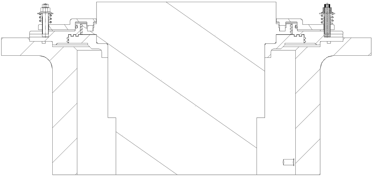
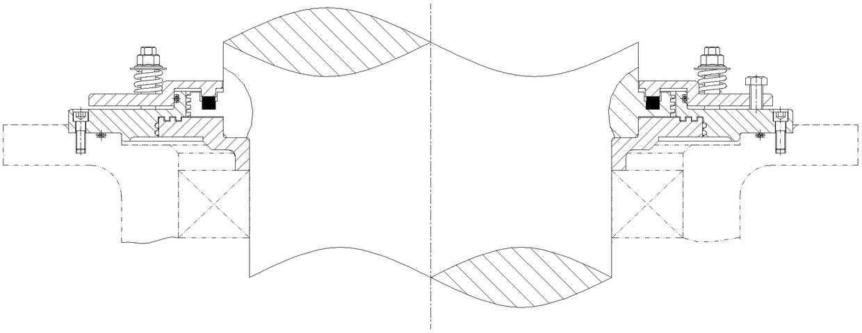
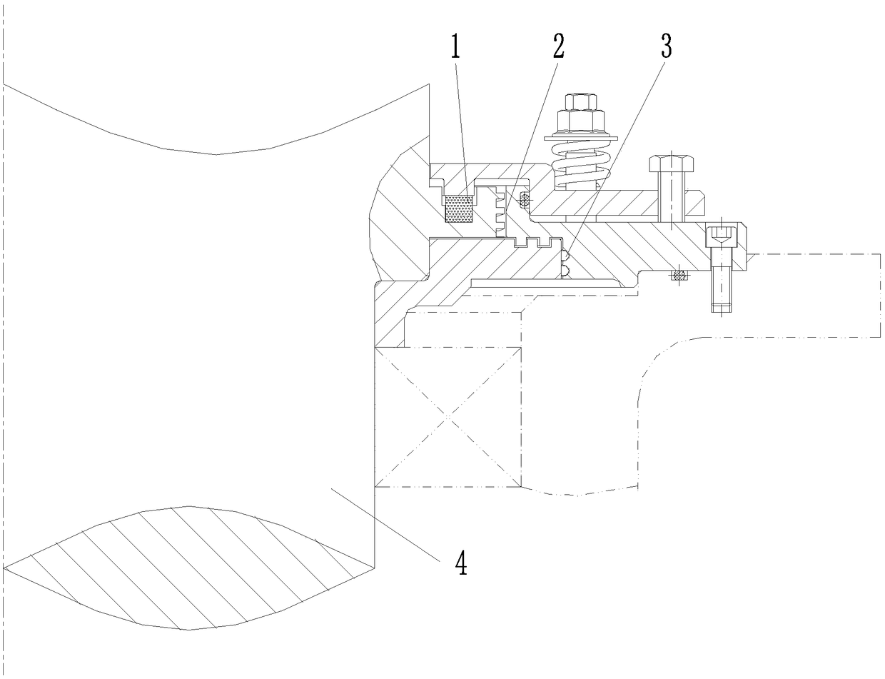
[0034] Large high-speed geotechnical centrifuge main shaft 4 dynamic sealing structure, including:

[0035] The spiral seal structure 2; the spiral seal structure 2 is composed of the main shaft 4 and the static ring 21, there is a gap between the main shaft 4 and the static ring 21, and a multi-headed rectangular thread 312 is provided on the outer diameter side of the shaft ring of the main shaft 4. When the centrifuge is working, The multi-head rectangular thread 312 is used to drive down the sealing medium;

[0036] Packing seal structure 1; packing seal structure 1 is composed of main shaft 4, gland 12, and packing 11. In the ring groove 311; above the filler 11, an annular gland 12 for compressing the filler 11 is arranged;

[0037] Multi-channel labyrinth seal structure 3; the labyrinth seal structure 3 is composed of a moving ring 31 and a stat...

Embodiment 2

[0042] Example 2, such as Figure 4 as shown,

[0043]The difference between this embodiment and Embodiment 1 is that the inner part of the moving ring 31 is located at the lower part of the shaft ring of the main shaft 4, the outer part of the moving ring 31 is located at the lower part of the inner part of the static ring 21, and the outer part of the static ring 21 is located at the bottom of the moving ring 31. The outside of the outer part; the inner part of the gland 12 is located at the top of the main shaft 4 collar, and the outer part of the gland 12 is located at the top of the static ring 21; the outer part of the static ring 21 passes through a plurality of second rings evenly arranged along its circumferential direction. The screw 22 is installed on the frame; the gland 12 is installed on the static ring 21 through a plurality of first screws 14 uniformly arranged along its circumferential direction; The compression mechanism 13 for the compression and loosening ...

Embodiment 3

[0044] Example 3, such as Figure 4 as shown,

[0045] The difference between this embodiment and Embodiment 2 is that the first screw 14 is a jacking screw.


PUM


Abstract

The invention discloses a dynamic sealing structure of a main shaft of a large high speed geotechnical centrifuge, which has strong adaptability, including a combined sealing form of a multi-channel labyrinth sealing structure, a one-channel spiral sealing structure and a one-channel stuffing sealing structure. The dynamic sealing structure of the main shaft of the large high speed geotechnical centrifuge can be applied to vacuum dynamic seal and achieve oil seal under atmospheric pressure, and has long service life. The stuffing seals with wear are opened on demand through a structure of a first screw, a compaction mechanism and a gland combination, and are used only in a limited period of time when a centrifuge chamber is pumped vacuum. The vacuum dynamic seal has strong reliability, andis provided with a compression mechanism with springs in design to ensure that after the stuffing is worn out, the gland can still press the stuffing. The replacement and switching operation of the compression mechanism is simple. Arc grooves and T-shaped grooves corresponding to the compression mechanism are respectively arranged on the gland and a static ring, thereby being convenient to replace the compression mechanism. The compression is designed with a limit sleeve to guarantee the same compression amount of the springs in each compression mechanism and further reduce the difficulty ofmanual operations.

Description

technical field [0001] The invention belongs to the technical field of geotechnical centrifuges, and in particular relates to a dynamic sealing structure for a main shaft of a large-scale high-speed geotechnical centrifuge. Background technique [0002] In the field of geotechnical engineering, the geotechnical centrifugal model test is to place the scaled geotechnical model (the size of each direction is 1 / n of the original soil) in a high-speed rotating geotechnical centrifuge, and use n times the acceleration of gravity (also known as ng ) to reproduce the stress state of the original soil (for related information, see: Jia Puzhao. Steady-state acceleration simulation experimental equipment-introduction and design of centrifuges [M]. Beijing: National Defense Industry Press, 2013). In recent years, the scale of geotechnical centrifuges has become larger and larger, and the centrifugal acceleration that can be achieved is also higher and higher. Large-scale, high-accelerat...

Claims


Application Information

Patent Timeline
Patent Type & Authority Applications(China)
IPC IPC(8): B04B7/00F16J15/16
CPCF16J15/16B04B7/00
Inventor 许元恒冉光斌洪建忠陈良军王新伦李心耀王鑫磊
Owner GENERAL ENG RES INST CHINA ACAD OF ENG PHYSICS
Why Eureka
Try Eureka