Flared flange pipe connecting system

A connection system and flanged pipe technology, applied in the field of flaring flange pipeline connection system, can solve problems such as long construction period, complicated welding process, pipeline leakage, etc., to reduce maintenance costs, ensure normal operation, and pass rate high effect

Inactive Publication Date: 2019-01-29
弗通流体科技(上海)有限公司
View PDF8 Cites 1 Cited by
  • Summary
  • Abstract
  • Description
  • Claims
  • Application Information

AI Technical Summary

Problems solved by technology

[0008] The technical problem to be solved by the present invention is to provide a flaring flange pipeline connection system, which can solve the problems of complicated welding process, easy leakage of pipeline and long construction period in the welding flange system in the prior art

Method used


Image

  • Flared flange pipe connecting system
  • Flared flange pipe connecting system

Examples


Embodiment Construction

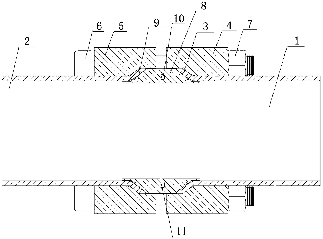
[0029] Such as figure 2 As shown, a flaring flange pipeline connection system includes a first branch pipe 1 and a second branch pipe 2, and the ends of the first branch pipe 1 and the second branch pipe 2 are respectively provided with tapered flares 3 , the first branch pipe 1 and the second branch pipe 2 are connected through a connection mechanism. The connection mechanism includes a first flange 4, a second flange 5, a first sealing cone 8, and a second sealing cone 9, and the first sealing cone 8 and the second sealing cone 9 both include a conical section and a cylindrical section, The conical section of the first sealing cone 8 is close to the inner end face of the tapered flare 3 of the first branch pipe 1, and the cylindrical section of the first sealing cone 8 stretches out from the tapered flare 3 of the first sealing cone 8; The conical section of the second sealing cone 9 is in close contact with the inner end surface of the tapered flare 3 of the second branch...


PUM


Abstract

The invention discloses a flared flange pipe connecting system. The flared flange pipe connecting system comprises two or more branch pipes. A conical flared opening is outwards formed in the end of each branch pipe. Every two adjacent branch pipes are connected through a connecting mechanism. Each connecting mechanism comprises a first flange, a second flange, a first seal conical body and a second seal conical body. The first seal conical bodies and the second seal conical bodies each comprise a conical section and a cylindrical section. The first flanges and the second flanges are arrangedon the different branch pipes. Each first flange is connected with the corresponding second flange through bolts and nuts. According to the flared flange pipe connecting system, spinning flaring is conducted on the end of each pipe through a flaring machine, so that the conical flared openings are formed; and by means of close matching of the first flanges, the second flanges, the first seal conical bodies, the second seal conical bodies, bolts and nuts, a safe and zero-leakage pipe system can be formed.

Description

technical field [0001] The invention relates to the technical field of pipeline connection systems, in particular to a pipeline connection and sealed flared flange pipeline connection system with an outer diameter of 50 mm to 273 mm and a maximum working pressure of 210 kg. Background technique [0002] Traditionally, the welding flange system is usually used for pipeline connection and sealing with an outer diameter of 50mm-273mm and a working pressure of up to 210kg. The flat welded pipe and the grooved welded pipe are respectively welded to two ends of different pipes, and then the flanges are respectively set on the front flat steps of the flat welded pipe and the grooved welded pipe. The structure of the welding flange system is as follows: figure 1 As shown, including flat welded pipe 1', grooved welded pipe 2', flange 3', sealing ring 4', bolt 5', nut 6', by tightening the bolt 5' and nut 6', the flange 3' is stressed, The flat welded pipe 1' and the grooved welded ...

Claims


Application Information

Patent Timeline
Patent Type & Authority Applications(China)
IPC IPC(8): F16L23/032F16L23/22
CPCF16L23/032F16L23/22
Inventor 李焕华
Owner 弗通流体科技(上海)有限公司
Why Eureka
Try Eureka