Plunger pump

A plunger pump and plunger technology, which is applied in the direction of pump control, pump components, variable capacity pump components, etc., can solve the problems of increased use cost, large footprint, and large volume of double-pump confluence unloading valve

Active Publication Date: 2019-02-15
东营盛昶石油机械有限公司
View PDF5 Cites 4 Cited by
  • Summary
  • Abstract
  • Description
  • Claims
  • Application Information

AI Technical Summary

Problems solved by technology

[0002] The plunger pump is a hydraulic power component widely used in the hydraulic system. In most working conditions of the existing mechanical equipment, the plunger pump has the requirements of low pressure and large flow, high pressure and small flow. There are two solutions in the prior art. The first One is to use two plunger pumps, one large and one small, which are respectively driven by two motors, one large and one small. When the pressure of the hydraulic system reaches a certain pressure value, the large motor is turned off through the electronic control program so that the large pump is not working. , this kind of scheme needs to be equipped with two motors, which occupies a large area and has a large installed power, which increases the cost of use; the second scheme is to use double pumps and double pump confluence unloading valves, and the double pumps are driven by one motor , when the pressure of the hydraulic system reaches a certain pressure value, the double-pump confluence unloading valve is controlled by the electronic control program to unload the large-displacement pump outlet in the double-connected pump. Due to the high price of the double-connected pump, this kind of scheme The double-pump confluence unloading valve is large in size and high in cost, which also increases the cost of use
In addition, the above two solutions are only suitable for medium and low pressure hydraulic systems, that is, the pressure is lower than 35MPa. For hydraulic systems with system pressure greater than 35MPa, there is no good solution in the prior art

Method used


Image

  • Plunger pump
  • Plunger pump
  • Plunger pump

Examples


Embodiment Construction

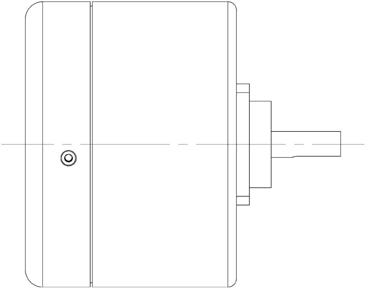
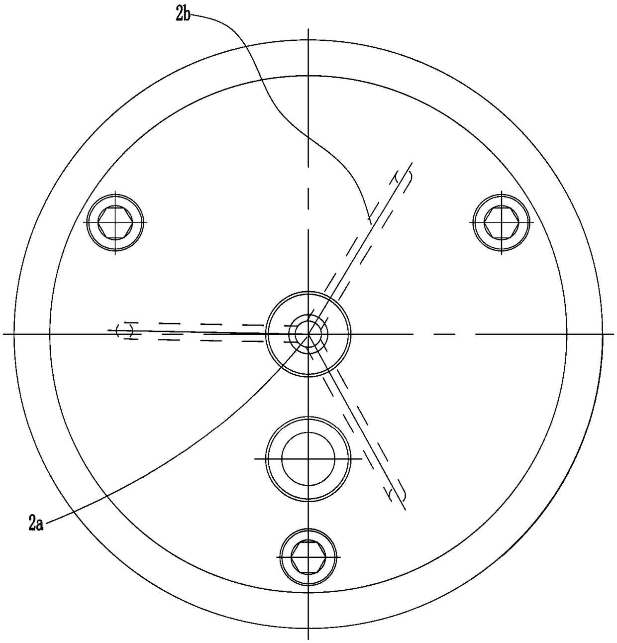
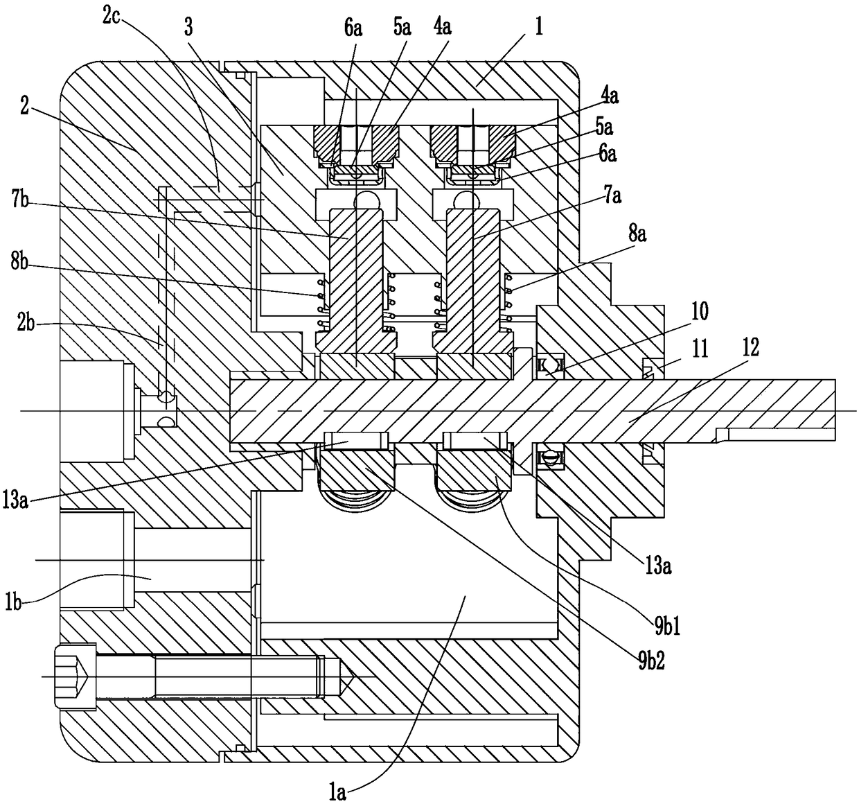
[0031] see Figure 1-11 As shown, a plunger pump includes a pump body 2, and a pump casing 1 installed on the right end surface of the pump body 2, and an oil inlet chamber 1a is formed between the pump casing 1 and the right end surface of the pump body 2. The left end surface of the pump body 2 is provided with an oil inlet hole 1b communicating with the oil inlet chamber 1a; the right end surface of the pump body 2 is rotatably connected with a rotating shaft 12 protruding from the pump casing 1, and the oil inlet chamber 1a is inside the pump body On the right end surface of 2, three variable plunger modules 001 are evenly installed with the rotating shaft 12 as the center, and the first shaft sleeves arranged side by side and coaxially are installed eccentrically on the rotating shaft 12 through the pin key 13a in the oil inlet chamber 1a 9b1 and the second sleeve 9b2.

[0032] The variable plunger module 001 includes a mounting block 3, a first plunger 7a, a second plun...


PUM


Abstract

The invention discloses a plunger pump. The plunger pump comprises a pump body and a pump shell mounted on the right end surface of the pump body. An oil inlet cavity is formed between the pump shelland the right end surface of the pump body, an oil inlet hole is formed in the left end face of the pump body, a rotating shaft is rotatably connected to the right end surface of the pump body, a plurality of variable plunger modules are mounted on the right end surface of the pump body in the oil inlet cavity, and a first shaft sleeve and a second shaft sleeve are eccentrically mounted on the rotating shaft in the oil inlet cavity; the variable plunger modules each include a mounting block, a first plunger, a second plunger, a first spring, a second spring, a first oil suction check valve assembly, a second oil suction check valve assembly and a variable control valve assembly; and a second oil outlet hole is formed in the central position of the left end surface of the pump body, a plurality of third oil outlet holes are formed in the pump body, and the pump body is internally provided with a fourth oil outlet hole. The plunger pump is not only compact in size and low in cost, but also can be applied to high pressure.

Description

technical field [0001] The invention relates to the technical field of hydraulic pumps, in particular to a plunger pump. Background technique [0002] The plunger pump is a hydraulic power component widely used in the hydraulic system. In most working conditions of the existing mechanical equipment, the plunger pump has the requirements of low pressure and large flow, high pressure and small flow. There are two solutions in the prior art. The first One is to use two plunger pumps, one large and one small, which are respectively driven by two motors, one large and one small. When the pressure of the hydraulic system reaches a certain pressure value, the large motor is turned off through the electronic control program so that the large pump is not working. , this kind of scheme needs to be equipped with two motors, which occupies a large area and has a large installed power, which increases the cost of use; the second scheme is to use double pumps and double pump confluence un...

Claims


Application Information

Patent Timeline
Patent Type & Authority Applications(China)
IPC IPC(8): F04B53/10F04B49/22
Inventor 不公告发明人
Owner 东营盛昶石油机械有限公司
Why Eureka
Try Eureka