

Device and method for detecting quality of filter
A technology for testing equipment and filters, applied in the field of filters, can solve the problems of poor accuracy of testing results, manual fixation of filters, and time-consuming transfer, achieving convenient operation, reducing power source requirements, and accurate and reliable testing results. Effect
- Summary
- Abstract
- Description
- Claims
- Application Information
AI Technical Summary
Problems solved by technology
Method used
Image

Examples
Embodiment 1
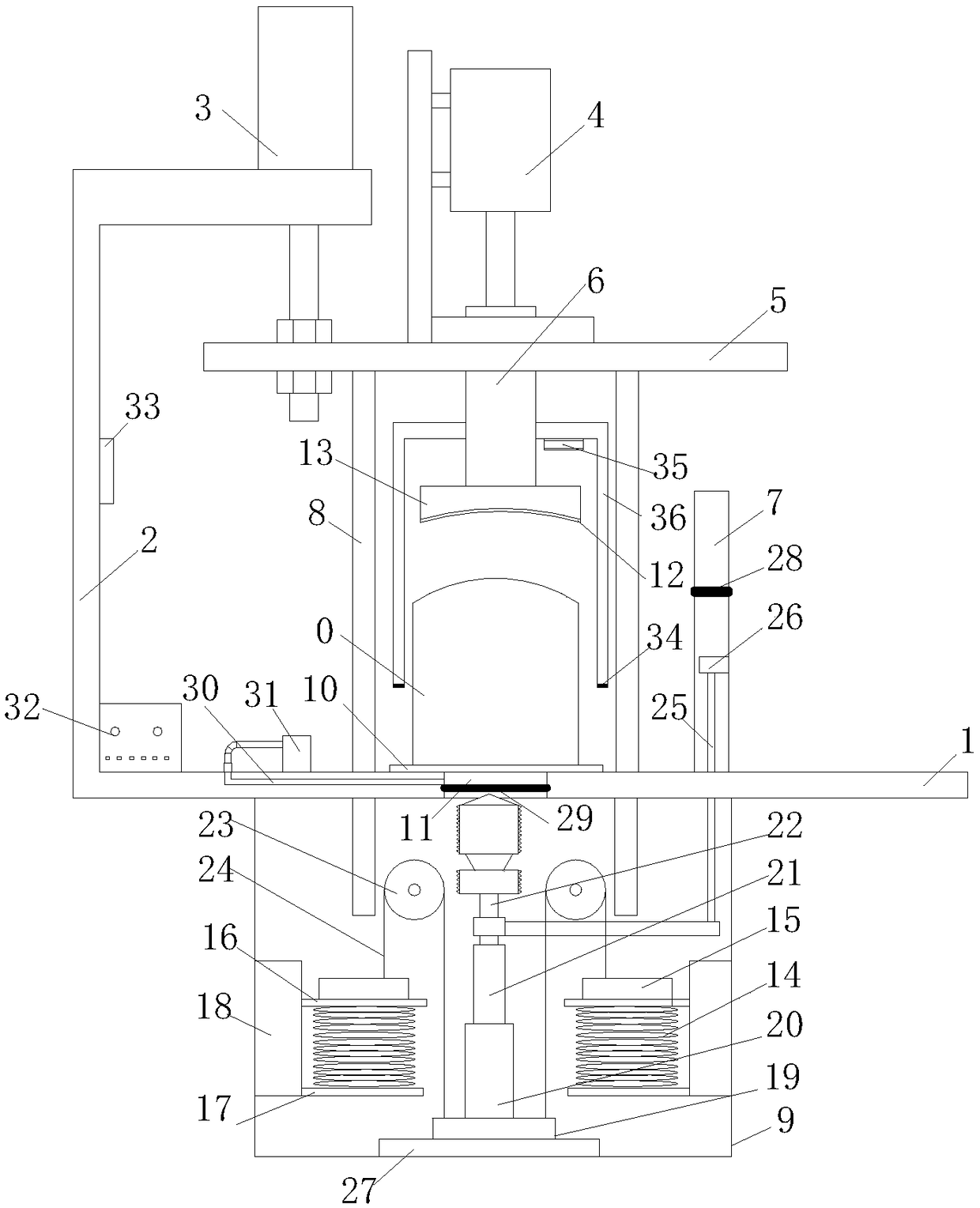
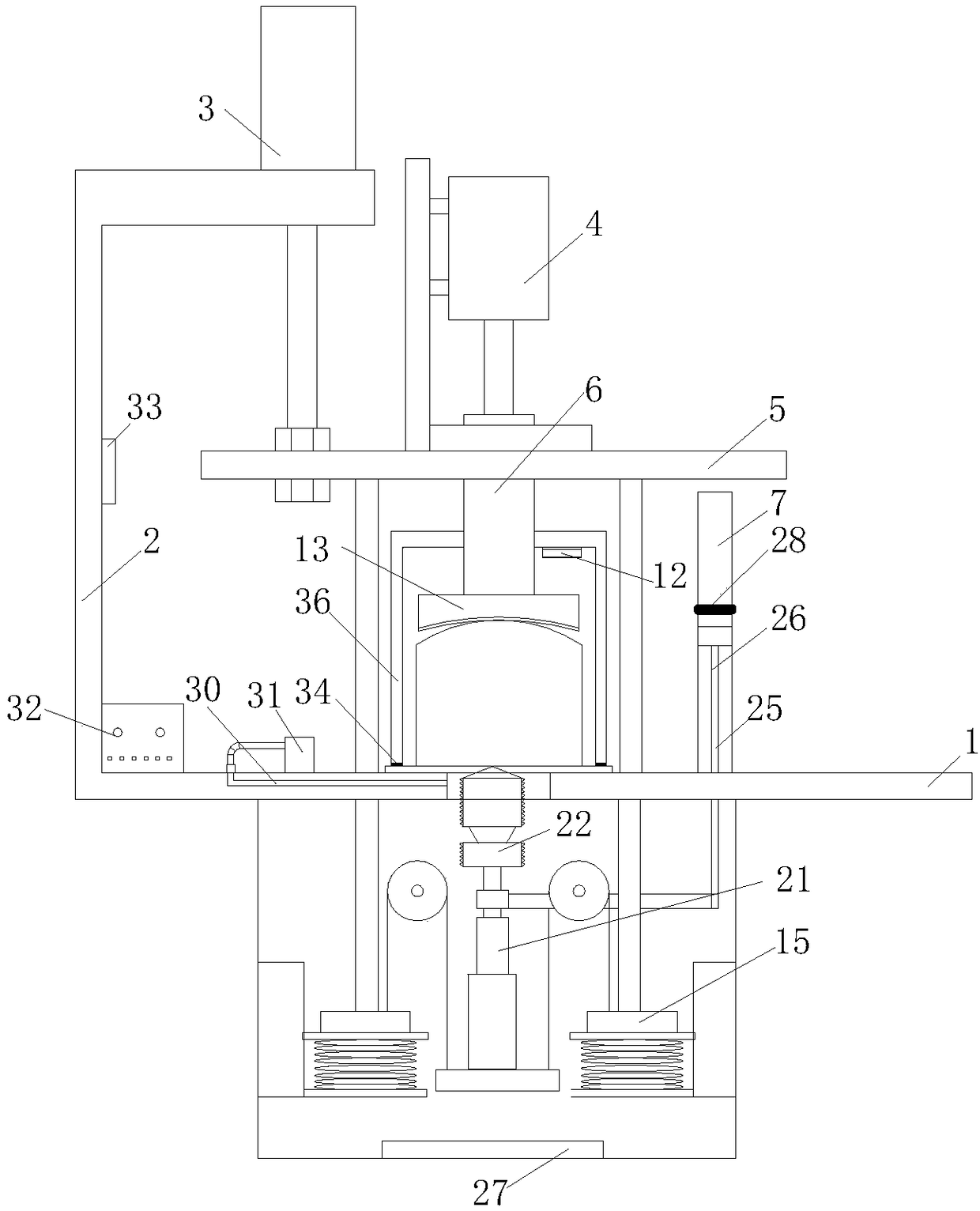
[0042] combine figure 1 and figure 2 , a kind of filter quality detection equipment that the present invention proposes, comprises frame, is used for detecting the thread quality detection unit of oil hole thread quality, is used for the tightness detection unit of detection tightness, controller 32 and loudspeaker 33.
[0043] The frame includes a workbench 1, an upper bracket 2 and a lower bracket 9, the bearing plate 5 is located above the workbench 1, the bearing plate 5 is driven to move up and down by the cylinder 3 on the upper bracket, and the positioning block 13 is rotatably connected to the bearing plate 5, The positioning block 13 is driven and rotated by the motor 4 on the carrier plate 5; the first through hole 11 for the tap 22 to pass through is opened on the workbench 1; The second through hole communicated with the first through hole 11; the lower bracket 9 is connected with a first lifting plate 19, the first lifting plate 19 is connected with a sleeve 20,...
Embodiment 2
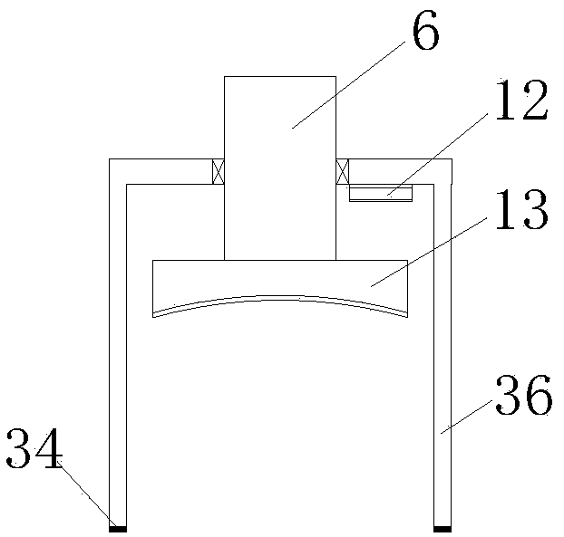
[0058] combine figure 1 , the difference between this embodiment and embodiment 1 is that this embodiment also discloses: combining figure 1 , 4 , the workbench 1 is penetratingly provided with a guide hole, the guide rod 8 is penetrated in the guide hole, and its upper end is connected to the bottom of the bearing plate 5; the second lifting plate 15 is slidably connected to the lower bracket 9, which is located on the first lifting plate 19 On one side of the guide rod 8, and on the movement stroke of the guide rod 8, a spring is connected between the second lifting plate 15 and the lower bracket 9; , the other end is connected on the second lifting plate 15 after passing through the guide wheel 23.
[0059] When the cylinder 3 drives the bearing plate 5 to move downward, the guide rod 8 moves downward thereupon. After the guide rod 8 contacts the second lifting plate 15, the guide rod 8 drives the second lifting plate 15 to move downward. Since the first lifting plate 1...
Embodiment 3
[0063] combine figure 1 The difference between this embodiment and Embodiment 1 is that this embodiment also discloses that: the lower bracket 9 is vertically connected with the first slide rail, and the first lifting plate 19 is fitted on the first slide rail. The cooperation between the first lifting plate 19 and the first slide rail enables the first lifting plate 19 to move on a predetermined path, so as to avoid the phenomenon that the detection process cannot be performed normally due to the displacement of the first lifting plate 19 .
[0064] The lower bracket 9 in the present embodiment is also connected with a lifting plate support 18, the lifting plate support 18 is fixedly connected with a lower spring support pad 17, and is slidably connected with an upper spring support pad 16, and the second lifting plate 15 is connected to the upper spring. On the supporting pad 16 , the spring 14 is connected between the lower spring supporting pad 17 and the upper spring supp...
PUM
 Abstract
Description
Claims
Application Information