
Grid disconnection and connection smooth switching control method for virtual synchronous generator
A technology of virtual synchronization and smooth switching, which is applied to the parallel feeding arrangement of a single network, electrical components, circuit devices, etc., can solve problems such as power grid impact, and achieve the effect of smooth grid connection and operation stability.
Patent Information
- Authority / Receiving Office
- CN · China
- Patent Type
- Applications(China)
- Current Assignee / Owner
- Publication Date
- 2019-03-19
- Estimated Expiration
- Not applicable · inactive patent
Smart Images
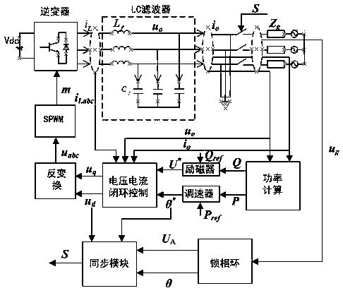
Figure 1 
Figure 2 
Figure 3
Abstract
Description
technical field
[0001] The invention specifically relates to a control method of a micro-grid distributed power supply based on virtual synchronous generator technology, and belongs to the field of control technology in new energy power generation. Background technique
[0002] With the global energy crisis and environmental pollution becoming more and more serious, clean energy such as solar energy and wind energy has received more and more attention. While vigorously developing distributed energy, the problems of distributed energy when connected to the grid have also attracted the attention of experts and scholars. The general distributed energy utilization is mainly connected to the grid through the inverter. Compared with the traditional synchronous generator, the grid-connected inverter has a fast response speed, lacks the moment of inertia and damping effect, and is not convenient for grid adjustment. Furthermore, the control methods of grid-connected inverters are d...
Examples
Embodiment Construction
[0019] The principle and specific implementation of the present invention will be described below in conjunction with the accompanying drawings.
[0020] figure 1 It is the topology of the main circuit of the microgrid inverter and its control structure diagram. By controlling the inverter, the oscillation of the inverter output voltage and current can be avoided when the inverter is switched from grid to grid, and the stable operation of the system can be protected to the greatest extent. .
[0021] Concrete implementation steps of the present invention are as follows:
[0022] Step 1, collect the grid voltage e within a switching cycle ga 、e gb 、e gc , the capacitor voltage u output by the microgrid inverter oa , u ob , u oc , bridge arm side inductor current i La i Lb i Lc and the output side current i oa i ob i oc , the grid voltage u in the synchronous rotating coordinate system is obtained by coordinate change gd , u gq , grid phase angle θ g , capacitor ...